Abstract:
With the rapid development of automotive intelligence and networking, on-board electronic systems are becoming increasingly complex, which puts forward higher requirements for the rate, reliability and anti-interference ability of communication transmission. Optical fiber harnesses, with their advantages of high speed, low loss, anti-electromagnetic interference and lightweight, are gradually becoming the ideal choice for in-vehicle communication systems. This article systematically analyzes the technical features, application advantages and implementation plans of optical fiber harnesses, and looks forward to their development prospects, providing a reference for the upgrade of automotive communication systems.
Introduction
At present, functions such as autonomous driving, Internet of Vehicles and high-definition entertainment have driven a sharp increase in the volume of in-vehicle data, posing challenges to traditional copper wire transmission in terms of speed and stability. Optical fiber communication technology, with its outstanding performance, provides an effective solution for building a new generation of vehicle-mounted networks. This article conducts an analysis from the dimensions of technical principles, application scenarios and system solutions, explores the role of optical fiber harnesses in promoting the upgrade of automotive communication, and looks forward to their prospects for large-scale application.
Technical Overview of Optical Fiber Harnesses
Optical fiber harnesses use light waves as the transmission carrier and rely on optical fiber media to achieve signal transmission. Their core advantages lie in high speed, high reliability, low loss and resistance to electromagnetic interference, fully matching the communication requirements of vehicle systems for large data volume and high real-time performance. Its communication link is mainly composed of optical fiber connectors and optical fiber conductors, which work together to ensure the stable transmission of signals.
1.1 Optical Fiber Connector
Optical fiber connectors are core passive components for achieving active optical fiber connections. They are composed of key structures such as optical fiber reinforcement, alignment, elastic docking, locking, and optical cable fixation (see Figure 1). The core working principle is as follows: Ceramic pins and ceramic sleeves are used to achieve precise alignment of optical fibers. The elastic alignment force is provided by the spring in the pre-compressed state - during the connection, the pins retract to generate secondary compression, ensuring that the two pins are always in a compressed contact state and guaranteeing the stability of the connection. This structural design enables the optical fiber connector to feature reliable insertion and extraction as well as low loss, making it suitable for the usage requirements of vehicle-mounted environments.
1.2 Optical Fiber Conductor
Optical fibers have a cylindrical structure and are composed of three layers: the core, the cladding, and the coating (see Figure 2). Their transmission core relies on the principle of total light reflection: when light is incident from the core with a high refractive index (optically dense medium) onto the cladding with a low refractive index (optically sparse medium), if the incident Angle is greater than the critical Angle, all the light will be reflected back to the core, achieving leak-free signal transmission.
The core technical features of optical fibers can be summarized in six points:
(1) Outstanding transmission efficiency: Fast transmission speed, long distance, capable of simultaneously carrying massive amounts of data, far exceeding traditional wires;
(2) Strong anti-interference ability: It transmits optical signals rather than electrical signals, is not affected by electromagnetic interference, and ensures stable signal quality;
(3) Wide frequency band: Supports ultra-high-speed data transmission, meeting the parallel communication requirements of multiple systems in vehicles;
(4) Extremely low loss: The theoretical transmission loss can be as low as less than 0.0035 dB per kilometer, achieving long-distance transmission without attenuation.
(5) High security: No electromagnetic radiation, not easy to be eavesdropped on, suitable for sensitive data transmission scenarios in vehicles;
(6) Lightweight and miniaturization: Compared with copper cables, it is smaller in volume and lighter in weight, facilitating on-board layout and maintenance, and reducing the overall burden on the vehicle.
The advantages of optical fiber harnesses in the intelligent application of automobiles
When the transmission rate of traditional copper wires reaches over 10 GB/s, the wire diameter needs to be thickened to meet the requirements. This will directly lead to an increase in the overall vehicle weight and cost, which is contrary to the development trend of automotive lightweighting and low cost. While enhancing communication performance, optical fiber harnesses perfectly avoid the aforementioned drawbacks. Their core advantages are specifically reflected in four aspects:
(1) Transmission rate outperforms traditional wires: Optical fiber harnesses can transmit millions of megabytes of data per second, easily meeting the large data volume transmission requirements of autonomous driving, high-definition entertainment, etc. However, the maximum speed of traditional copper wire networks is only 10GB/s, which is difficult to meet the communication upgrade requirements of intelligent vehicles.
(2) Extremely low transmission loss: The loss of optical fibers per kilometer is usually less than 0.0035 dB/m, ensuring high-quality signals even during long-distance transmission. The transmission loss of traditional copper wires reaches 0.5 dB/m, and the signal attenuation is severe during long-distance transmission, requiring additional relay equipment.
(3) Electromagnetic interference immunity: The light wave transmission characteristics make it immune to electromagnetic interference generated by the vehicle's internal engine, sensors and other electronic devices, and it will not cause interference to other on-board electronic systems, ensuring communication stability and compatibility with the vehicle's electronic systems.
(4) Facilitating vehicle lightweighting: Automotive optical fibers represented by plastic optical fibers (POF) are much lighter than traditional metal wires, which can significantly reduce the vehicle's overall weight, improve fuel economy or driving range, and align with the development direction of automotive energy conservation.
Application scenarios of optical fiber harnesses in Automobiles
Optical fiber harnesses have been widely applied in communication, industry, medical care and other fields, but their implementation in the automotive field still faces challenges such as insufficient basic theories, lack of technical specifications, unclear test standards and limited application practices. Its in-vehicle applications need to focus on adapting to the environmental characteristics of different areas of the car and provide targeted solutions.
3.1 Application of Optical Fiber Harnesses in the Layout Area
The usage environment of automobiles is complex, and the requirements for the temperature resistance, water resistance and vibration resistance of wiring harnesses vary significantly in different regions. Based on the risk of liquid contact, the vehicle layout area can be divided into three categories, corresponding to different protection levels of the wiring harness:
(1) Wet zone: The area that is bound to come into contact with liquids during regular use, such as the chassis, engine room and other areas outside the passenger cabin. In rainy and snowy weather, the wire harness connectors in this area are prone to contact with rainwater and sewage, and the highest level of waterproof protection is required.
(2) Potential wet areas: These are areas that may come into contact with liquids in specific scenarios, such as the floor of the passenger compartment, door handrails, and seat surfaces. They may come into contact with liquids due to opening the door on rainy days, spilling water cups, or dripping condensate water, and require moderate waterproof protection.
(3) Absolute dry zone: An area where there is almost no possibility of liquid contact during normal use, such as the interior of the dashboard and the interior of the ceiling, which has the lowest requirements for waterproof sealing.
The waterproof sealing requirements of the three aspects decrease successively from the wet area to the dry area, which is the core basis for the layout of the optical fiber harness.
3.2 Optical Fiber Harness Application Solutions
The application of optical fiber harnesses in vehicles must simultaneously meet the requirements of electrical performance and mechanical performance, with a focus on addressing the three core challenges of temperature, vibration, and waterproofing. The specific solutions are as follows:
(1) Optical fiber cables: Multi-dimensional adaptation to vehicle environments
For high-temperature environments:
① Select high-temperature resistant materials (such as silicone wire, XLPE wire) to ensure stable insulation at high temperatures;
② It adopts a double-layer coating + ultraviolet curing process to enhance high-temperature resistance.
③ Optimize the layout plan to avoid the engine exhaust pipe and high-temperature vortex areas, and use high-temperature resistant heat insulation coatings (such as aluminum foil fiberglass tubes), while enhancing the aging resistance.
In response to waterproofing requirements: A multi-layer protective structure design is adopted - the outermost plastic sheath provides basic waterproofing and mechanical protection, the inner metal sheath enhances the pressure resistance and waterproofing capacity, and a water-swelling water-blocking layer is set in the middle (which rapidly expands to close the path when water invades). The optical fiber is wrapped with grease inside the cable core to absorb trace amounts of moisture, ensuring the optical fiber remains dry in all aspects. For instance, the automotive optical harness solution of Yangtze Optical Fibre and Cable Co., Ltd. features quartz multimode fibers that meet automotive standards in terms of bending (radius 10mm), tensile strength (150N), temperature adaptability (-40℃ to 125℃), aging (125℃/3000h), and vibration (V3).
(2) Optical fiber connector: Dual upgrades for temperature resistance and water resistance
Enhance temperature resistance:
① Design a heat dissipation structure, reserve metal components for heat conduction, add heat dissipation fins to the casing, and use a metal casing to improve heat dissipation efficiency;
② High-temperature resistant materials are selected. The shell and internal structure are made of high-quality engineering plastics resistant to medium and low temperatures, and key components are made of special alloy materials to enhance high-temperature resistance and anti-deformation capabilities. For instance, the non-contact optical connectors launched by Letas Optics offer higher repeatability in insertion and extraction, longer lifespan, lower insertion loss, and lower dust sensitivity compared to traditional products.
Enhanced waterproof performance: Adopt a combination solution of heat shrink tubing and sealant - place the heat shrink tubing over the connection part, heat it to shrink and closely adhere to the joint and optical fiber, then evenly apply sealant to fill the gap. After drying and hardening, it forms a double protection to prevent moisture and contaminants from entering.
(3) Hybrid connection scheme
It adopts a "fiber optic + electrical connection" hybrid mode: the fiber optic is responsible for high-speed data transmission, and the electrical connection port is responsible for the power supply function of the sensor, taking into account both transmission efficiency and power supply stability, and meeting the requirements of multi-device collaborative operation in vehicles.
Conclusion
The development of intelligent automobiles has put forward requirements for high speed, low loss, anti-interference and lightweight communication systems, which has driven the upgrade of traditional copper wires to optical fiber harnesses. Optical fiber harnesses, with their core advantages such as transmission efficiency, anti-interference ability and lightweight, perfectly match the communication requirements of vehicles. Through implementation measures such as regional protection design, material and process optimization, and hybrid connection schemes, the adaptation to the complex on-board environment has been achieved.
In the future, with the improvement of basic theories, the standardization of technical norms, and the accumulation of application practices, optical fiber harnesses will be applied on a large scale in the automotive industry, becoming the communication support for core functions such as autonomous driving and the Internet of Vehicles, injecting key impetus into the intelligent upgrade of automobiles, and leading in-vehicle communication into a new era of high speed, reliability and efficiency.
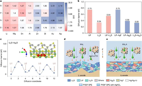 Figure 1. Schematic illustration of the component screening and functional mechanism of the ductile SEI during solid-state battery cycling.
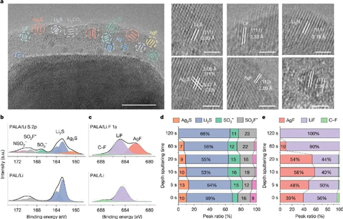
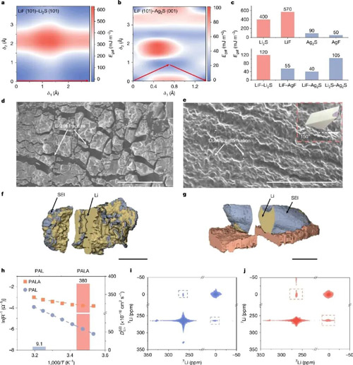 Figure 3. Exceptional plastic deformability and mechanical stability of the inorganic-rich ductile SEI.