Real-Time EPR Results at the Bench

For many U.S. labs, collecting data quickly and efficiently is critical. A desktop EPR brings real-time EPR spin analysis into everyday workflows, allowing scientists to move from sample preparation to results faster. Researchers can monitor dynamic processes such as free radical reactions, material characterization, or biological spin studies with immediate feedback.

Unlike traditional floor-standing EPR systems, a benchtop EPR allows rapid setup and operation without requiring extensive training or dedicated lab space. This makes fast EPR measurement and high-throughput spin analysis accessible for more researchers.
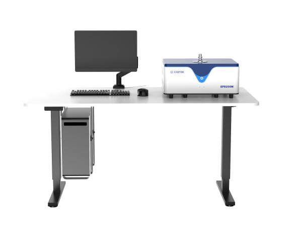
 

CIQTEK Benchtop EPRModern Benchtop EPR


Why Real-Time Spin Analysis Matters

Many experiments in chemistry, materials science, and biology involve species that change rapidly. Rapid EPR experiments can provide insights that would otherwise take hours or days. With a desktop EPR, researchers can:

  • Acquire spectra quickly with minimal downtime

  • Adjust experimental conditions based on real-time data

  • Iterate experiments more efficiently

  • Reduce sample waste and lab bottlenecks

By enabling real-time EPR measurement, desktop EPR systems support more agile decision-making and accelerate research cycles.


What Makes Desktop EPR Ideal for Modern Labs

Benchtop EPR spectrometers combine a compact design with high performance. Key advantages include:

- Compact EPR Form Factor

A desktop system fits on a standard lab bench, ideal for shared facilities or labs with limited space.

- Intuitive Operation

User-friendly software and controls allow researchers to perform spin analysis without specialized training, supporting multiple users in busy labs.

- Fast EPR Measurement

High-performance detection and streamlined workflows enable rapid spectral acquisition for both solid and liquid samples, making rapid EPR experiments practical.

- Reliable Performance

Modern desktop EPR systems maintain sensitivity and resolution comparable to larger instruments while providing the flexibility of a benchtop unit.

These features make desktop EPR a practical choice for labs that value efficiency and accuracy.


Real U.S. Lab Cases: Faster Workflows and Immediate Feedback in Practice

Real-time EPR is not just a theoretical advantage. In several U.S. research laboratories, desktop EPR systems are already being used to shorten experiment cycles and deliver immediate data feedback, especially in environments where access to large shared instruments is limited or inefficient.


At Cornell University, a CIQTEK benchtop EPR system was introduced to support both biomedical research and teaching. One of the key motivations was workflow efficiency. Instead of scheduling time on a centralized EPR facility, researchers could perform spin analysis directly at the lab bench, immediately after sample preparation. This allowed rapid checks of radical signals and faster decisions on whether experiments should proceed, repeat, or be adjusted. For students and researchers alike, real-time EPR access reduced waiting time and made data interpretation part of the same working session, rather than a separate step days later.


A similar efficiency-driven approach can be seen at Northwestern University, where a CIQTEK desktop EPR200M is used in materials and chemistry research. Researchers value the ability to run fast EPR measurements without interrupting ongoing experiments. Having a benchtop EPR nearby enables quick verification of paramagnetic species during synthesis or material processing, helping teams respond immediately to unexpected results and optimize conditions on the spot.


At the University of Texas at Dallas, the adoption of the CIQTEK desktop EPR system supports both research and instructional use. For teaching labs and student projects, real-time EPR measurements mean that experiments can be completed and discussed within a single lab session. For research users, the system provides rapid feedback during routine spin analysis, improving throughput and reducing dependency on shared, high-demand instrumentation.


Across these U.S. labs, the common theme is not simply access to EPR, but speed and control over the experimental timeline. Desktop EPR systems allow researchers to move from sample to spectrum quickly, integrate data analysis into daily workflows, and maintain momentum in fast-paced research environments.

 

A screenshot from a user feedback video of the CIQTEK desktop EPR200M from Cornell University.A screenshot from a user feedback video of the CIQTEK desktop EPR200M from Cornell University


How Desktop EPR Boosts Laboratory Productivity

Integrating a benchtop EPR into lab workflows can transform research efficiency. Key benefits include:

  • Shorter setup and measurement times

  • Faster turnaround for real-time EPR experiments

  • Ability to handle higher sample throughput

  • Flexibility for both research and teaching applications

With desktop EPR, labs can achieve rapid EPR experiments and continuous data flow without waiting for traditional instruments.


Performance and Value in One System

A desktop EPR spectrometer delivers strong, high-performance EPR capabilities at a significantly lower cost than many legacy systems. The combination of compact design, quick measurement, and streamlined operation makes benchtop EPR an attractive option for laboratories that need reliable spin analysis without heavy infrastructure or long setup times.

Within this category, CIQTEK desktop EPR systems stand out for their exceptional price-to-performance balance. By focusing on the core measurement needs of modern research labs, CIQTEK offers benchtop EPR instruments that provide robust sensitivity, stable performance, and real-time data access at a price point that is difficult to match. This allows more research groups to adopt EPR spectroscopy as a routine tool rather than a limited shared resource.


For U.S. laboratories conducting spin analysis, CIQTEK benchtop EPR systems deliver immediate results from bench to insight, helping teams maximize research output while keeping capital investment under control. The result is a practical, efficient solution that aligns with both scientific goals and budget realities.
You Can Extend System Life Without Replacing the Magnet

If your aging EPR spectrometer is 10, 15, or even 20 years old, a full system replacement is often unnecessary.
In many U.S. laboratories, the magnet remains stable and reliable, while performance limitations come from outdated electronics, probes, and software.

By performing a practical EPR spectrometer upgrade, laboratories can restore performance, modernize workflows, and control costs. This approach has already been implemented in real projects and is proving to be both cost-effective and efficient.


Why the Magnet Is Usually Not the Limiting Factor

Magnets are designed for long-term operation and often remain stable for decades with proper care.

In most cases, the magnet provides:

  • Stable magnetic field strength

  • Acceptable field homogeneity

  • Reliable day-to-day operation

The main limitations come from other parts of the system that age faster, such as electronics, control units, and software. This is why many laboratories choose to upgrade their EPR spectrometer without replacing the magnet, focusing on electronics and controls instead of full replacement.


Common Problems with Aging EPR Systems in U.S. Labs

These challenges are common in an aging EPR spectrometer that has been in use for many years.

- Reduced Signal Quality

A lower signal-to-noise ratio makes weak signals harder to detect and increases experiment time.

- Outdated Software and User Interfaces

Legacy software may not run smoothly on modern operating systems and lacks automation features that labs now expect.

- Increasing Maintenance Pressure

Replacement parts are harder to source, and service visits take longer and cost more.

- Limited Support for Modern Experiments

Advanced experiments often require improved timing control, better signal processing, and more flexible system configuration.

These issues typically point to outdated electronics and controls rather than the magnet itself.


What Can Be Upgraded in an EPR Spectrometer

A modern EPR system upgrade focuses on components that limit performance rather than replacing the entire instrument.

- Console and Control Electronics

Upgrading the console improves stability, acquisition speed, and compatibility with modern computers. This is often the most impactful step in the upgrade old EPR spectrometer workflow.

- Microwave Electronics and Detection Chain

Modern microwave electronics reduce noise and improve signal stability, resulting in clearer and more reliable spectra.

- Probes and Resonators

New probe designs can significantly improve sensitivity and ease of use, especially for routine measurements.

- Software and Automation

Updated software simplifies daily workflows, supports automated experiments, and makes the system easier to operate for students and shared facilities.


Upgrade Versus Buying a New System

For many laboratories, upgrading is a practical alternative to full system replacement.

With an EPR system upgrade, labs can:

  • Keep a functioning magnet

  • Reduce capital investment

  • Shorten downtime

  • Minimize disruption to ongoing research

When the magnet remains stable, an EPR upgrade without replacing the magnet often delivers most of the benefits of a new system at a fraction of the cost. This approach is a cost-effective EPR upgrade that many U.S. laboratories are now choosing.


A Real EPR Modernization Case from CIQTEK

A real example comes from Queen Mary University of London, where CIQTEK completed an official EPR spectrometer modernization service.

The laboratory was operating an aging EPR spectrometer that no longer met current research needs. While the magnet was stable, outdated control electronics and system modules limited performance and usability.

Instead of replacing the entire system, the laboratory chose CIQTEK EPR modernization and upgrade service. CIQTEK completed on-site installation, optimized the system, and provided user training.

After the upgrade:

  • System stability improved

  • Daily operation became more efficient

  • The laboratory extended the usable life of its EPR system

  • The high cost and disruption of full replacement were avoided

This demonstrates that upgrading a legacy EPR system is already being implemented successfully in active research environments.


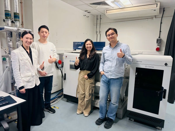
CIQTEK completed the EPR spectrometer modernization service at Queen Mary University of LondonCIQTEK completed the EPR spectrometer modernization service at Queen Mary University of London


Why CIQTEK EPR Upgrades Are Cost-Effective

Budget planning is a critical concern for U.S. laboratories. CIQTEK EPR upgrade service is designed to be cost-effective by focusing on performance-limiting components rather than replacing the entire instrument.

Each upgrade is evaluated based on the existing system's condition, ensuring that resources are used efficiently. This makes the service a truly cost-effective EPR upgrade for labs looking to extend the life of their instruments.


How Long Does an EPR Upgrade Take

Compared with full system replacement, EPR upgrades typically require much less downtime.

  • Hardware preparation is done in advance

  • On-site installation and system validation are efficient

  • User training is included

This allows labs to resume experiments quickly and maintain research continuity.


Moving Forward

If your aging EPR spectrometer still has a reliable magnet but does not meet modern research needs, a cost-effective EPR upgrade is a practical solution.


CIQTEK EPR modernization and upgrade service helps laboratories extend system life, improve performance, and protect research budgets while minimizing disruption. For many U.S. EPR users, upgrading is not a compromise but a smart, strategic decision. 

Learn more about CIQTEK EPR modernization and upgrade service


CIQTEK EPR Upgrade WorkflowCIQTEK EPR Upgrade Workflow

To enhance connection efficiency and maintenance convenience for industrial equipment, WAIN officially launches the M15 Quick-Connect Series. This series is designed to address major challenges in on-site installation and long-term maintenance. Its innovative structure is reflected in two core design highlights:


Core Design Highlights

Rapid Locking Mechanism for Higher Installation Efficiency

The connector housing adopts a direct-push quick-connect mechanism. During mating, no manual twisting of the coupling nut is required—simply push to engage, and it locks automatically. This significantly shortens installation time and reduces the difficulty of operating in tight or restricted spaces.

Detachable Contacts for Simplified Maintenance

The contacts use cold-crimp technology and are designed to be separable from the insert. After crimping the cable, the contact can be snapped directly into the side of the contact carrier—quick and intuitive. During maintenance, individual damaged contacts can be replaced without removing the entire connector, offering a more economical and flexible service solution.


Key Features & Advantages


1

Stable Electrical Performance

  Rated  at 63V / 5A, suitable for general industrial applications.

2

Reliable Connection Quality

  Cold-crimped contacts ensure stable, robust performance across diverse industrial environments.

3

Flexible Model Options

  Available in multiple configurations—including assembly-type (panel-mount compatible) and flange   versions (front/rear panel mounting)—to support various installation needs.

4

Multiple Pin-Count Options

  Offered in 9-pin, 12-pin, and 15-pin configurations to meet different signal and power requirements.


Typical Application Scenarios


◆ Industrial automation equipment (e.g., servo motors, robotic arms)
◆ Control systems requiring fast connection and easy maintenance
◆ Modular machine systems


The WAIN M15 Quick-Connect Series delivers a more efficient connectivity solution for both equipment manufacturing and on-site servicing through its optimized structural design.

For more information, please visit the WAIN official website (www.wainelectric.com) or contact us directly.


·END·

WAIN is not only manufacturing, but also creating!

Any questions and ideas related to industrial connectors,

we welcome to discuss with you.

Strengthening Ties with a Leading European University

CIQTEK is pleased to announce its official recognition as a donor to the Jean-Marie Lehn Foundation, part of the University of Strasbourg, France.

As one of Europe's leading research institutions, and ranked No. 1 in the European Union for Chemistry in the 2025 Shanghai Ranking, the University of Strasbourg plays a central role in advancing scientific research and innovation.

The Jean-Marie Lehn Foundation aims to foster collaboration between academia and industry, support scientific research, and nurture young talent. The Foundation promotes innovation, knowledge exchange, and partnerships that advance chemistry, materials science, and related fields.


CIQTEK Becomes Official Donor to the University of Strasbourg

CIQTEK logo is now featured on the Foundation's donor page, reflecting the company's commitment to supporting world-class academic development. Source: Jean-Marie Lehn Foundation website


Expanding Collaboration in EPR Research

This milestone also highlights CIQTEK's expanding collaboration with the University of Strasbourg in Electron Paramagnetic Resonance (EPR) spectroscopy. CIQTEK will sponsor the ARPE EPR 10th Summer School, to be held in France from June 22–26, 2026.

During the event, researchers and students will gain hands-on experience with the CIQTEK EPR200M benchtop EPR spectrometer and explore CIQTEK’s advanced floor-stand EPR solutions through real-time remote demonstrations. More details coming soon!


Growing CIQTEK's Presence in France and Europe

Looking ahead, CIQTEK will further strengthen its presence in France and Europe, enhancing brand visibility, expanding collaborations with universities and laboratories, and delivering innovative EPR technologies that accelerate research in materials science, chemistry, and spin-related fields.


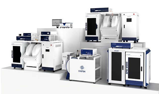
CIQTEK EPR SeriesCIQTEK EPR Spectrometer Series

In today’s fast-paced world, keeping track of your health can be challenging, but the S200 Smartwatch makes it effortless. Designed with advanced Murata high-precision piezoelectric air pump technology, it delivers accurate and stable blood pressure readings with a sealed, waterproof airbag system—bringing medical-grade monitoring right to your wrist. Combined with the flagship TI AFE4950 sensor and nano superconducting ECG glass, the S200 captures precise ECG signals, heart rate, and blood oxygen levels in real-time, helping you stay on top of your health.


Beyond core metrics, the S200 features mini health checks, emotional and fatigue detection, and 24-hour sleep monitoring. It even supports women’s health, body composition analysis, non-invasive glucose tracking, breathing exercises, and body temperature monitoring. Multiple sport modes, including step counting, calorie tracking, and distance measurement, encourage an active lifestyle while providing clear progress data.


On the lifestyle side, the S200 integrates Alipay offline payment, NFC door access, Bluetooth calls, and SOS emergency alerts. Its smart voice assistant and weather forecast make everyday tasks easier, while the vivid AMOLED HD display ensures you never miss a detail. With S200, health management, fitness tracking, and daily convenience are seamlessly combined—empowering you to lead a smarter, more active life.


Nuclear fusion is considered a key future energy source due to its high efficiency and clean energy output. In fusion reactors, water cooling systems are widely used because they are technically mature, cost-effective, and have excellent cooling performance.

However, a major challenge remains: under high temperature and high pressure, water and steam strongly corrode structural materials. While this problem has been studied in fission reactors, fusion environments are more complex. The unique high-intensity, unevenly distributed magnetic fields in fusion devices interact with corrosion processes, creating new technical challenges that need detailed research.

To address this, Associate Professor Peng Lei's team from the University of Science and Technology of China conducted an in-depth study using the CIQTEK scanning electron microscope (SEM) and dual-beam electron microscope. They built high-temperature magnetic-field steam corrosion and high-temperature water corrosion setups. Using SEM, EBSD, and FIB techniques, they analyzed oxide films formed on CLF-1 steel after 0–300 hours of steam corrosion at 400°C under 0T, 0.28T, and 0.46T magnetic fields, and after 1000 hours of high-temperature water corrosion at 300°C.


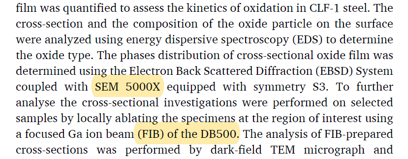
The study used CIQTEK SEM5000X ultra-high-resolution field-emission SEM and the FIB-SEM DB500The study used CIQTEK SEM5000X ultra-high-resolution field-emission SEM and the FIB-SEM DB500


The study found that the oxide films form a multilayer structure, with a chromium-rich inner layer and an iron-rich outer layer. Film formation occurs in five stages: initial oxide particles, then floc-like structures, formation of a dense layer, growth of spinel structures on the dense layer, and finally, spinel cracking into laminated oxides. The presence of a magnetic field significantly accelerates corrosion, promotes the transformation of outer magnetite (Fe₃O₄) into hematite (Fe₂O₃), and enhances laminated oxide formation. This work was published in Corrosion Science, a top-tier journal in the field of corrosion and materials degradation, under the title: "Magnetic field effects on the high-temperature steam corrosion behavior of reduced activation ferritic/martensitic steel."


Magnetic field effects on the high-temperature steam corrosion behavior of reduced activation ferritic/martensitic steel.


Surface Oxide Film Characterization

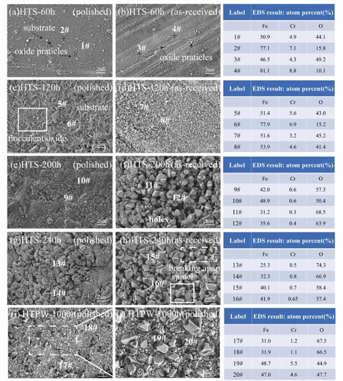
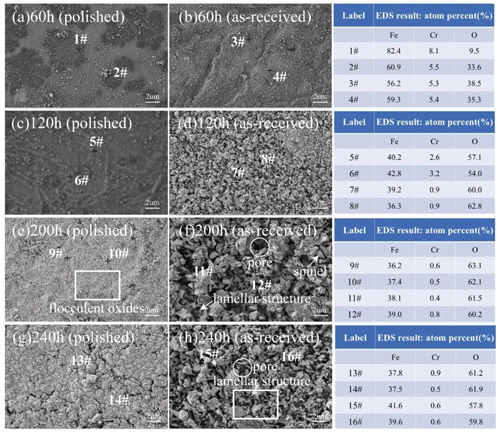
In high-temperature steam (HTS), CLF-1 steel surfaces show different corrosion states over time. On polished surfaces, early-stage oxidation (60 h) appears as small, dispersed particles. The Fe/Cr ratio is similar to the substrate, indicating that the oxide layer is not yet complete. By 120 h, floc-like oxides appear. At 200 h, a dense oxide layer forms, with new oxide particles and local spinel structures on top.

Rough surfaces corrode faster. Early floc-like oxides are finer and more evenly distributed. By 200 h, they transform into spinel structures, showing a stronger difference from polished surfaces. In high-temperature, high-pressure water (HTPW), polished surfaces display similar spinel structures. Spinel in HTPW is denser and more numerous, while spinel in HTS is larger in size.

When a magnetic field is applied (0.28 T on polished, 0.46 T on rough), corrosion changes further. After 60 h, oxide particles appear on both surfaces, more on rough surfaces. By 120 h, polished surfaces have particle-like oxides, while rough surfaces develop fine floc-like films. At 200 h, rough surfaces show spinel cracking and layered structures perpendicular to the surface, with many pores forming. By 240 h, layers become denser and well-aligned. EDS analysis shows that under magnetic fields, Fe/Cr decreases and oxygen increases over time. Cr content drops at 120 h, earlier than in non-magnetic conditions, showing that magnetic fields accelerate the formation of the iron-rich outer layer.


Figure 1. SEM images and EDS point scans (#1–#20) of CLF-1 surfaces under HTS and HTPW.Figure 1. SEM images and EDS point scans (#1–#20) of CLF-1 surfaces under HTS and HTPW.


Figure 2. SEM images and EDS point scans (#1–#16) of CLF-1 surfaces exposed to magnetic fields: polished (0.28 T), rough (0.46 T).Figure 2. SEM images and EDS point scans (#1–#16) of CLF-1 surfaces exposed to magnetic fields: polished (0.28 T), rough (0.46 T).


Oxide Film Phase Analysis

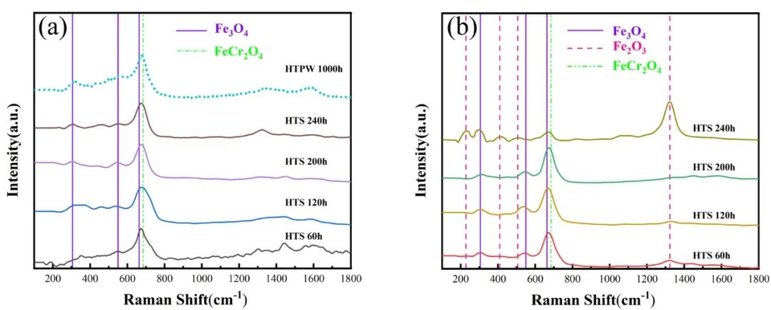
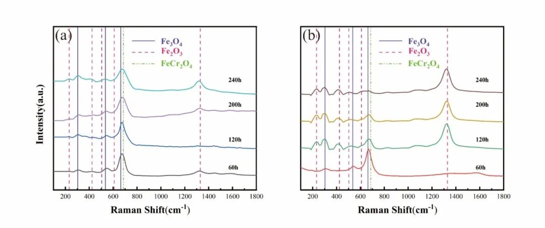
Figures 3 and 4 show Raman spectra of CLF-1 steel oxide films in HTS, HTPW, and under magnetic fields. Without a magnetic field, films in both HTS and HTPW are mainly spinel structures composed of Fe₃O₄ and FeCr₂O₄. The Raman peaks (302, 534, 663, 685 cm⁻¹) overlap, making differentiation difficult. Hematite (Fe₂O₃) appears only on rough HTS surfaces after 240 h.

Under a magnetic field, oxidation accelerates. Polished surfaces show small Fe₂O₃ peaks only at 240 h, while rough surfaces show Fe₂O₃ as early as 120 h, increasing by 240 h. Meanwhile, Fe₃O₄ and FeCr₂O₄ peaks weaken, indicating faster hematite formation.


Figure 3. Raman spectra of oxide films on CLF-1 under HTS and HTPW: (a) polished; (b) rough.Figure 3. Raman spectra of oxide films on CLF-1 under HTS and HTPW: (a) polished; (b) rough.


Figure 4. Raman spectra under magnetic field HTS: (a) polished (0.28 T); (b) rough (0.46 T).Figure 4. Raman spectra under magnetic field HTS: (a) polished (0.28 T); (b) rough (0.46 T).


Cross-Section Oxide Film Characterization

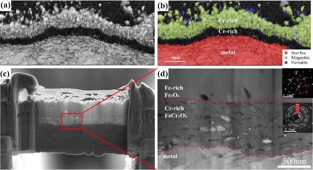
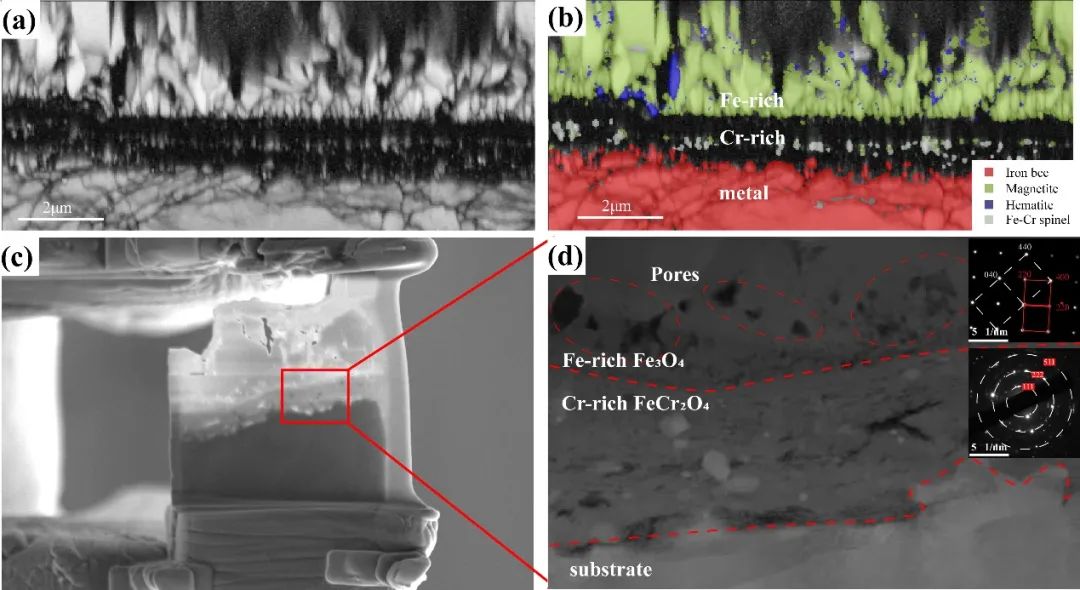
EBSD analysis of rough surfaces after 300 h HTS corrosion (Figure 5a, b) shows a three-layer oxide structure: a thin, discontinuous Fe₂O₃ outer layer, a dense Fe₃O₄ middle layer, and a black chromium-rich layer between Fe₃O₄ and the substrate. FIB-prepared cross-sections (Figure 5c, d) and TEM/SAED analysis confirm that the chromium-rich layer is FeCr₂O₄, and the iron-rich layer is Fe₃O₄. Gaps at the interfaces indicate phase separation and pore formation during oxidation evolution.


Figure 5. Microstructure and phase distribution of cross-section oxide films on rough CLF-1 surfaces after 300 h HTS: (a) EBSD contrast; (b) EBSD phase map; (c) FIB cross-section; (d) dark-field TEM and SAED.Figure 5. Microstructure and phase distribution of cross-section oxide films on rough CLF-1 surfaces after 300 h HTS: (a) EBSD contrast; (b) EBSD phase map; (c) FIB cross-section; (d) dark-field TEM and SAED.


Figure 6 shows cross-sections under a magnetic field (HTS, 240 h). EBSD shows outer oxides composed of Fe₃O₄ and Fe₂O₃. Fe₃O₄ layers are vertically aligned with many pores, and Fe₂O₃ fills surface gaps. The chromium-rich layer between the outer layer and substrate is porous. Compared with non-magnetic conditions, films are looser with more pores, especially at layer interfaces and within the Fe-rich layer. SAED confirms that oxide films still consist of FeCr₂O₄ and Fe₃O₄ from inner to outer layers. Magnetic fields mainly affect film density and pore evolution, not phase composition.


Figure 6. Cross-section microstructure and phase distribution of rough CLF-1 surfaces under magnetic field HTS: (a) EBSD contrast; (b) EBSD phase map; (c) FIB cross-section; (d) dark-field TEM and SAED.Figure 6. Cross-section microstructure and phase distribution of rough CLF-1 surfaces under magnetic field HTS: (a) EBSD contrast; (b) EBSD phase map; (c) FIB cross-section; (d) dark-field TEM and SAED.


This study examines the effect of magnetic fields on CLF-1 steel corrosion after 300 h in 400°C HTS. It also compares oxide films formed under HTPW and HTS conditions. The findings provide important reference data for optimizing the corrosion resistance of fusion structural materials.

As the electrification of commercial vehicles and construction machinery accelerates, WAIN delivers a cutting-edge solution: our integrated metal-shell connectors designed specifically for high-voltage power distribution units (PDUs). Engineered for demanding environments, this series combines robust performance with installation efficiency.

Exceptional Load Capacity – Precision-engineered design supporting 1–4 core configurations, with a maximum voltage rating of 2000 V and current up to 450 A.

Comprehensive Protection – Certified IP67/IP6K9K sealing with 360° shielding to safeguard against harsh environmental conditions and electromagnetic interference.

Versatile Installation – Multiple keying options and straight or angled cable outlets ensure optimal compatibility and significantly reduce installation time.

Proven in the field, these connectors are already in bulk supply to multiple Tier 2 high-voltage component manufacturers, delivering stable performance and reliable integration. Today, they are enabling mass-production applications across a wide range of commercial vehicles and construction machinery, helping power the next generation of new energy transportation. 

How Does Megtron 6 M6 Material Solve Signal Loss Challenges in High-Frequency PCBs?


In the race for higher data speeds and greater bandwidth, signal loss is the ultimate enemy. As frequencies climb into the gigahertz range—common in 5G, radar, and high-speed computing—traditional PCB materials like FR-4 become a significant bottleneck. They absorb and degrade signals, leading to data errors, reduced range, and compromised system performance.


Panasonic Megtron 6 M6 laminate is engineered specifically to combat this enemy. It solves signal loss challenges through a fundamental improvement in its core material properties, primarily by minimizing Dielectric Loss and ensuring Impedance Stability. Let's break down the science behind it.


1. Taming the Primary Culprit: Ultra-Low Dielectric Loss (Df)

The most significant source of signal loss at high frequencies is not the conductor but the insulating substrate itself, a phenomenon known as Dielectric Loss.


The Problem with FR-4: Standard FR-4 has a Dissipation Factor (Df) in the range of 0.020 at 1 GHz. Think of Df as a measure of how much electrical energy the substrate converts into wasted heat. A higher Df means the material "absorbs" more of your signal, attenuating it as it travels along the trace.


The Megtron 6 Solution:Megtron 6 M6 boasts an exceptionally low Df of 0.002 at 1GHz and a still-impressive 0.0037 at 13GHz. This is an order-of-magnitude improvement.


Analogy: If FR-4 is a rough, muddy path that saps a runner's energy, Megtron 6 is a smooth, high-tech track. The signal experiences far less resistance from the substrate, allowing it to travel farther and with greater integrity.


Result: This directly translates to lower insertion loss, enabling longer trace lengths, higher data rates (crucial for 400G/800G optics), and more powerful signals in applications like 77GHz automotive radar.


2. Ensuring Predictable Performance: Stable Dielectric Constant (Dk)

The Dielectric Constant (Dk) is a measure of how much the insulating material slows down the electrical signal and affects its impedance. An unstable Dk is a silent killer of signal integrity.


The Problem with Inconsistent Materials: In many materials, the Dk can vary with frequency, temperature, or even the manufacturing lot. This variability makes it incredibly difficult for engineers to design precise impedance-controlled lines (like the 50-ohm traces in our 12-layer PCB). An unexpected shift in Dk during operation can detune your circuit, cause impedance mismatches, and lead to signal reflections.


The Megtron 6 Solution: Megtron 6 high speed PCB offers a stable and predictable Dk of ~3.34 at 13GHz, with minimal change over a wide frequency range. This stability is engineered into the material's composition.


Result: Design engineers can model their high-speed circuits with extreme confidence. The impedance calculated in the simulation (e.g., the 4.31mil trace for a 50-ohm line on L3) will be the impedance fabricated on the actual board. This eliminates guesswork, reduces design iterations, and guarantees that eye diagrams remain open and well-defined.


12-Layer Megtron6 -M6 High Speed PCB


3. The Combined Effect: Enhanced Signal Integrity and System Bandwidth

The combination of a low Df and a stable Dk is what truly sets Megtron 6 apart. It's not just about losing less signal; it's about preserving the signal's quality.


Lower Attenuation: The low Df directly reduces the amount of signal amplitude lost per unit length.


Minimized Dispersion: The stable Dk ensures that different frequency components of a complex digital signal travel at the same speed. This prevents the "smearing" or spreading out of the signal pulse, which is critical for maintaining the shape of high-speed digital waveforms.


4. Supporting Factors: Thermal and Dimensional Stability

While not directly electrical, Megtron 6's thermal properties play a crucial supporting role in combating long-term performance degradation.


High Tg and Td: With a Glass Transition Temperature (Tg) >185°C and a Thermal Decomposition Temperature (Td) of 410°C, Megtron 6 can withstand the high temperatures of multiple lead-free soldering cycles without breaking down.


Why this matters: If a material degrades thermally during assembly, its Dk and Df can permanently change, altering the performance of the finished PCB from the design intent. Megtron 6's robustness ensures the electrical properties you designed for are the ones you get after manufacturing.


Low CTE: Its controlled Coefficient of Thermal Expansion (16/16/45 ppm/°C) prevents excessive warping or delamination under thermal stress. This maintains the physical geometry of the impedance-controlled traces, which is essential for their consistent electrical performance.


Conclusion: A Material Engineered for the Gigahertz Era

In summary, Megtron 6 M6 solves high-frequency signal loss challenges by providing an ultra-low-loss dielectric "foundation" that is both stable and predictable. It directly attacks the primary sources of loss—dielectric absorption and impedance variation—that plague conventional materials.


By choosing a PCB built with Megtron 6, like the 12-Layer Megtron6-M6 High Speed 2.0mm Thick PCB, you are not just selecting a component; you are choosing a guaranteed level of signal fidelity. This allows your designs to achieve the performance boundaries required for the next generation of 5G infrastructure, autonomous vehicles, and high-performance computing systems.


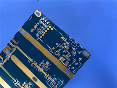
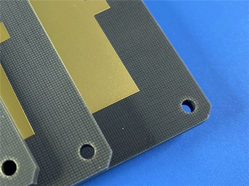
What Are the Key Benefits of Using F4BTMS450 Material in a 4-Layer RF PCB?


In the world of Radio Frequency (RF) and microwave electronics, the printed circuit board (PCB) substrate is far more than a passive platform for components; it is an integral part of the circuit's performance. Choosing the right material is critical, and for demanding applications, standard FR-4 is insufficient. The F4BTMS450 material represents a specialized high-frequency laminate that offers a suite of compelling advantages for a4-layer RF PCB design.


Here are the key benefits of using F4BTMS450:


1. Superior Signal Integrity with Stable Dielectric Constant

At RF frequencies, signal integrity is paramount. The dielectric constant (Dk orεr) of the substrate material directly controls the impedance of transmission lines (like microstrips and striplines) and the phase of signals. 


  • Tight Dk Tolerance: F4BTMS450 has a dielectric constant of 4.5 +/-0.09 at 10GHz. This exceptionally tight tolerance ensures that the impedance is consistent across the entire board and from one batch of boards to the next.


  • Benefit: Engineers can design with confidence, achieving precise impedance matching (e.g., 50Ωlines) without unexpected variations that can cause signal reflections, loss of power, and degraded system performance.


2. Extremely Low Loss for Enhanced Efficiency

As signals travel through the 4-layer F4BTMS450 PCB, some energy is absorbed by the dielectric material and converted into heat. This is measured by the Dissipation Factor (Df) or loss tangent.


  • Minimal Dielectric Loss: F4BTMS450 boasts an ultra-low dissipation factor of 0.0015 at 10GHz. This is an order of magnitude lower than standard FR-4.


Benefit: For a 4-layer RF PCB, this translates to:


  • Higher Efficiency: Less signal power is lost, which is crucial for battery-operated devices and high-power transmitters.


  • Improved Signal-to-Noise Ratio (SNR): Cleaner signals with less degradation over distance.


  • Better System Performance: In applications like radar and satellite communications, low loss directly increases range and sensitivity.


3. Exceptional Thermal and Dimensional Stability

RF systems, especially power amplifiers, generate heat, and equipment often operates in harsh environments with wide temperature swings.


  • Low Coefficient of Thermal Expansion (CTE): F4BTMS450 has a CTE of 12/12/45 ppm/°C (x/y/z). This low and balanced expansion profile is close to that of copper, reducing stress on plated through-holes (vias).


  • Stable Dk over Temperature: Its thermal coefficient of Dk is a low -58 ppm/°C. This means the dielectric constant remains stable over a wide temperature range (-55°C to 150°C).


Benefit: The 4-layer PCB structure remains mechanically reliable, preventing via cracking and delamination. Electrically, the circuit performance (e.g., filter center frequency, phase response) remains predictable and stable regardless of operational temperature, which is vital for aerospace and defense applications.


4-Layer F4BTMS450 PCB


4. High Reliability for Demanding Environments

The operational environment for many RF applications is unforgiving. F4BTMS450 is engineered to meet these challenges.


  • Low Moisture Absorption (0.08%): Moisture ingress can drastically alter a material's Dk and increase loss. The very low moisture absorption of F4BTMS450 high frequency PCB ensures stable electrical performance even in humid conditions.


  • UL-94 V0 Flammability Rating: The material is self-extinguishing, enhancing the safety and reliability of the end-product.


Benefit: This combination makes the resulting 4-layer PCB highly reliable and suitable for critical systems in aerospace, spaceflight, and military radar, where failure is not an option.


5. Optimal Performance for Complex, Dense 4-Layer Designs

The specific construction of a 4-layer board using F4BTMS450 leverages all the benefits above into a practical, high-performance multilayer solution.


  • Improved EMI Shielding: A typical4-layer stackup (Signal-Ground/Power-Signal) allows for dedicated ground planes. These planes act as shields, containing RF energy within the board and protecting sensitive signals from external noise.


  • Enhanced Power Integrity: The solid internal power plane provides a low-inductance power distribution network, which is crucial for stable voltage to high-speed digital and RF components.


  • Material Consistency in Multilayer Bonding: The use of compatible prepreg (likeRO4450F) in the stackup ensures a homogeneous dielectric environment, maintaining consistent electrical properties throughout all four layers.


Conclusion: A Foundation for High-Frequency Success

In summary, selecting F4BTMS450 for a 4-Layer RF PCB is a strategic decision to build your design on a foundation of performance, stability, and reliability. Its key benefits—stable dielectric constant, extremely low loss, outstanding thermal performance, and high environmental resilience—directly address the most critical challenges in RF and microwave design. By minimizing electrical losses and maintaining predictable behavior under stress, this material enables the creation of superior, high-performance systems for the most demanding applications in aerospace, telecommunications, and defense.

With the rapid expansion of new energy, mining, metallurgy, and electroplating industries, nickel pollution in water bodies has become a growing threat to environmental quality and human health. During industrial processes, nickel ions often interact with various chemical additives to form highly stable heavy-metal organic complexes (HMCs). In nickel electroplating, for example, citrate (Cit) is widely used to improve coating uniformity and brightness, but the two carboxyl groups in Cit readily coordinate with Ni²⁺ to form Ni–Citrate (Ni-Cit) complexes (logβ = 6.86). These complexes significantly alter nickel’s charge, steric configuration, mobility, and ecological risks, while their stability makes them challenging to remove with conventional precipitation or adsorption methods.

Currently, "complex dissociation" is regarded as the key step in removing HMCs. However, typical oxidation or chemical treatments suffer from high cost and complicated operation. Therefore, multifunctional materials with both oxidative and adsorptive capabilities offer a promising alternative.

Researchers from Beihang University, led by Prof. Xiaomin Li and Prof. Wenhong Fan, used the CIQTEK scanning electron microscope (SEM) and electron paramagnetic resonance (EPR) spectrometer to conduct an in-depth investigation. They developed a new strategy using KOH-modified Arundo donax L. biochar to efficiently remove Ni-Cit from water. The modified biochar not only showed high removal efficiency but also enabled nickel recovery on the biochar surface. The study, titled “Removal of Nickel-Citrate by KOH-Modified Arundo donax L. Biochar: Critical Role of Persistent Free Radicals”, was recently published in Water Research.


CIQTEK SEM & EPR Reveal a New Pathway for Nickel-Citrate Removal


Material Characterization

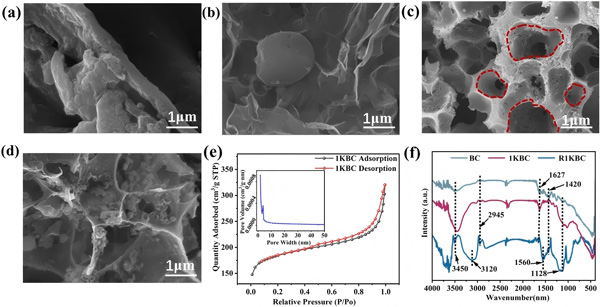
Biochar was produced from Arundo donax leaves and impregnated with KOH at different mass ratios. SEM imaging (Fig. 1) revealed:

  • The original biochar (BC) exhibited a disordered rod-like morphology.

  • At a 1:1 KOH-to-biomass ratio (1KBC), an ordered honeycomb-like porous structure was formed.

  • At ratios of 0.5:1 or 1.5:1, pores were underdeveloped or collapsed.

  • BET analysis confirmed the highest surface area for 1KBC (574.2 m²/g), far exceeding other samples.

SEM and BET characterization provided clear evidence that KOH modification dramatically enhances porosity and surface area—key factors for adsorption and redox reactivity.


Figure 1. Preparation and characterization of KOH-modified biochar.Figure 1. Preparation and characterization of KOH-modified biochar.


Performance in Ni-Cit Removal

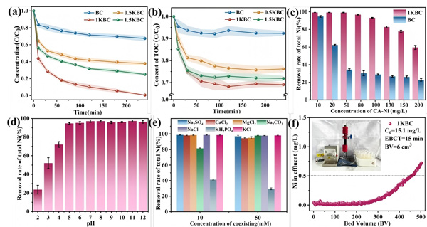
Figure 2Figure 2.
(a) Removal efficiency of total Ni by different biochars;
(b) TOC variation during Ni–Cit treatment;
(c) Effect of Ni–Cit concentration on the removal efficiency of 1KBC;
(d) Effect of pH on the removal performance of 1KBC;
(e) Influence of coexisting ions on Ni–Cit removal by 1KBC;
(f) Continuous-flow removal performance of Ni–Cit by 1KBC.
(Ni–Cit = 50 mg/L, biochar dosage = 1 g/L)


Batch experiments demonstrated strong removal performance:

  • At 50 mg/L Ni-Cit and 1 g/L material dosage, 1KBC removed 99.2% of total nickel within 4 hours, compared to 32.6% for BC.

  • TOC removal reached 31% for 1KBC, confirming that Ni-Cit undergoes complex dissociation followed by Ni²⁺ adsorption.

  • Even at 100 mg/L Ni-Cit, the removal efficiency remained above 93%.

  • 1KBC maintained excellent performance across a wide pH range (pH > 5).

  • Phosphate significantly inhibited removal due to solution acidification and competitive complexation with Ni²⁺.

  • In continuous-flow tests, a 1KBC-packed fixed-bed reactor operated for 6900 minutes, treating 460 bed volumes, while maintaining effluent Ni < 0.5 mg/L.


Post-Treatment Material Characterization

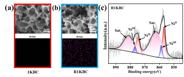
Figure 3. Morphology and EDS comparison of the material before (a) and after (b) Ni–Cit removal; (c) XPS spectra of surface Ni 2p after the removal process.Figure 3. Morphology and EDS comparison of the material before (a) and after (b) Ni–Cit removal;
(c) XPS spectra of surface Ni 2p after the removal process.


Recovered biochar (R1KBC) showed:

  • No significant morphological changes.

  • Uniform Ni distribution confirmed by EDS mapping.

  • XPS spectra displayed both Ni²⁺ and Ni³⁺ peaks, direct evidence of oxidative complex dissociation.


EPR-Based Identification of ROS

Figure 4. EPR measurementsFigure 4. EPR measurements:
(a) TEMP-trapped ¹O₂ generated by biochar;
(b, c) BMPO-trapped •OH and O₂•⁻ generated by biochar;
(d) Hyperfine splitting fitting analysis of the 1KBC signal in panel (c).


Using the CIQTEK EPR spectrometer, the team identified reactive oxygen species (ROS) generated on the biochar surface:

  • ¹O₂: strong TEMP–¹O₂ triple signal (1:1:1, AN = 17.32 G) observed only in 1KBC.

  • OH: BMPO–•OH quartet detected in both BC and 1KBC, but much stronger in 1KBC.

  • O₂•⁻: identified through BMPO–•OOH signals in methanol-containing systems.

1KBC produced significantly higher levels of ¹O₂, •OH, and O₂•⁻ than BC, confirming the enhanced redox activity induced by KOH modification.


Free Radical Quenching Experiments

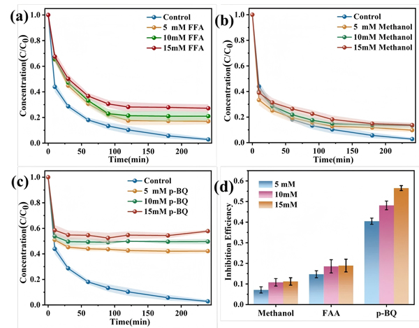
Figure 5.Figure 5.
(a) Effect of ¹O₂; (b) •OH; and (c) O₂•⁻ on Ni–Cit removal efficiency;
(d) Inhibition rates of different ROS on Ni–Cit removal.


By introducing quenchers, FFA (¹O₂), p-BQ (O₂•⁻), and methanol (•OH)—the team quantified the contributions of different ROS:

O₂•⁻ inhibition (55%) > ¹O₂ inhibition (17%) > •OH inhibition (12%)

This ranking indicates that O₂•⁻ plays the dominant role in Ni-Cit degradation and complex dissociation.


Role of PFRs and ROS Generation Mechanism

Figure 6.Figure 6.
(a) Detection of surface PFRs in biochar;
(b) Effect of PFR quenching on Ni–Cit removal by biochar;
(c) ¹O₂, (d) •OH, and (e) O₂•⁻ signals in 1KBC and TEA-treated samples;
(f) Schematic of ROS transformation pathways.


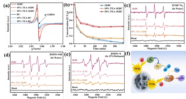
Persistent free radicals (PFRs) in biochar are closely linked to ROS formation. EPR results showed:

  • 1KBC exhibited much higher PFR concentration than BC.

  • PFRs had a g-value of 2.0034, characteristic of carbon-centered radicals adjacent to oxygen (e.g., phenoxy radicals).

  • Triethylamine (TEA) effectively quenched PFRs, reducing Ni-Cit removal efficiency to ~50% and drastically lowering ROS levels.

The mechanism (Fig. 6f):

  • Dissolved oxygen adsorbs onto the biochar surface.

  • PFRs transfer electrons to O₂, forming O₂•⁻.

  • O₂•⁻ initiates complex dissociation; subsequent ROS degrade the citrate ligand.


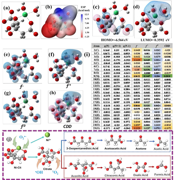
DFT Calculations and Mechanistic Insights

Figure 7.Figure 7.
(a) Optimized structure of Ni–Cit;
(b) Electrostatic potential (ESP) map;
(c) HOMO; (d) LUMO;
Fukui function isosurfaces of Ni–Cit:
(e) f⁻, (f) f⁺, (g) f⁰, (h) condensed dual descriptor (CDD), and (i) Fukui indices;
(j) Proposed degradation pathways of Ni–Cit.


Density functional theory (DFT) calculations clarified the molecular reaction pathways:

  • Frontier molecular orbital and Fukui function analysis revealed that the Ni center is prone to nucleophilic attack, while the citrate ligand undergoes electrophilic reactions.

  • O₂•⁻, with its strong nucleophilicity, targets the Ni center, breaking the Ni–Cit coordination.

  • Citrate ligands degrade through two ROS-mediated pathways.

These theoretical results align with EPR findings and support the proposed mechanism.


KOH-modified biochar (1KBC) achieved 99.2% Ni removal from 50 mg/L Ni-Cit solution within 4 hours. The modification significantly enhanced porosity, surface functionality, and, critically, the concentration of persistent free radicals. These PFRs activated dissolved oxygen to generate ROS, among which O₂•⁻ acted as the primary species driving Ni-Cit dissociation. Subsequent ROS degraded the citrate ligand, while released Ni²⁺ was adsorbed onto the biochar.

This study demonstrates a sustainable "one-step dissociation and recovery" approach for treating metal–organic complexes, offering strong potential for future real-world applications.