In the high-speed operation of 5G base stations and AI data centers, optical modules serve as information transmission hubs, and behind them lies an "invisible key component" - the quartz crystal oscillator (quartz crystal oscillator). A-Crystal Technology has been deeply engaged in this field, providing high-precision quartz crystal oscillator products to ensure the stable transmission of optical modules and exploring new opportunities in the wave of industry upgrading.

quartz crystal oscillator


The "Precision Timekeeper" of Optical Modules  

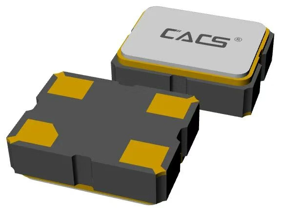
The core role of the Quartz Crystal Oscillator is to provide a reference clock for chips such as  DSP and  FPGA inside optical modules, ensuring coordinated operation of all components.  

• 100G optical modules require a frequency error of  ±20ppm and jitter <1ps  .  

• 800G/1.6T modules have stricter requirements: 156.25MHz high-frequency differential Crystal Oscillator, phase jitter <70 femtoseconds, and wide-temperature stability from -40℃ to 85℃.  

• If the Crystal Oscillator fails, it can directly cause abnormal optical power and a sharp increase in the bit error rate. Therefore, all products from A-Crystal Technology undergo rigorous high/low-temperature and vibration tests to ensure reliability.  


Cost Proportion and Market Space  

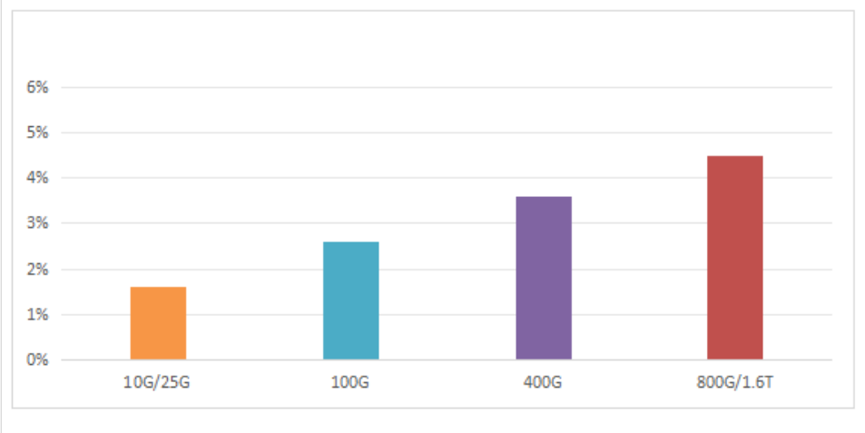
In optical modules of different rates, the cost proportion of Crystal Oscillators increases with higher performance requirements:  

•   10G/25G modules: 1%–2% proportion, compatible with A-Crystal Technology’s 25MHz Active Crystal Oscillator  .  

•   100G/400G modules: 2%–4% proportion, requiring A-Crystal Technology’s 156.25MHz Differential Crystal Oscillator  .  

•   800G/1.6T modules: 4%–5% proportion, matching A-Crystal Technology’s specialized models with wide-temperature and ultra-low jitter.  


The cost proportion of crystal oscillators for optical modules of different rates


In terms of the market, the global optical module market is expected to reach $23.5 billion in 2025, with Differential Crystal Oscillators driven by AI server optical modules reaching $1.9–4.9 billion. The demand for 800G optical modules is projected to exceed 10 million units in 2025, and 1.6T modules are expected to surpass 10 million units by 2026.  


Technology Trends and Competitive Landscape


Technology Directions  

• High Frequency : To adapt to 1.6T modules, A-Crystal Technology is developing higher-frequency Crystal Oscillator products.  

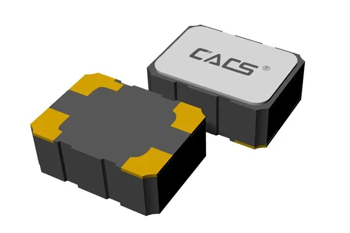
• Miniaturization: Package sizes are shrinking from 7.0×5.0mm to 1.6×1.2mm (A-Crystal Technology’s  2520 package products are already in mass application).  

• Wide Temperature Range: Expanding from commercial-grade 0℃~70℃ to industrial-grade -40℃~85℃ to meet the needs of complex scenarios.  

Competitive Landscape  

• International: Japanese companies Kyocera and Epson dominate the high-end OCXO (Oven-Controlled Crystal Oscillator) market, while the U.S.-based   SiTime captures the mid-to-low-end market with MEMS Crystal Oscillators.  

• Domestic: Some domestic manufacturers have achieved mass production of ultra-high-frequency Crystal Oscillators above 300MHz. However, the localization rate of 25G and high-end optical module Crystal Oscillators is only 10%, leaving significant room for substitution.  


Challenges and Opportunities  


Challenges: The contradiction between high-frequency and miniaturization, the balance between low jitter and low power consumption, and the demand for strong anti-interference. Through continuous efforts by its R&D team, A-Crystal Technology has broken through the bottlenecks.

Opportunities: The explosion of AI computing power drives optical module upgrades, increased support for domestic substitution policies, and rising demand for independent control of key components. A-Crystal Technology is entering a development window.  


Conclusion  

Although Quartz Crystal Oscillators account for only 1%–5% of the cost in optical modules, they are a critical component with far-reaching impact. With the widespread adoption of 800G/1.6T optical modules, the market size is expected to reach $2–5 billion. A-Crystal Technology is narrowing the gap with international competitors through technological breakthroughs and will become a key supporter of the optical module industry’s upgrade.  


Contact Us

Want to know more about A-Crystal’s Technology products?

Need selection the model or technical consultation?

Feel free to contact us via the following methods!


Tel: 0086-576-89808609  

Email: market@acrystals.com


Website: [www.acrystals.com](http://www.acrystals.com)

To enhance connection efficiency and maintenance convenience for industrial equipment, WAIN officially launches the M15 Quick-Connect Series. This series is designed to address major challenges in on-site installation and long-term maintenance. Its innovative structure is reflected in two core design highlights:


Core Design Highlights

Rapid Locking Mechanism for Higher Installation Efficiency

The connector housing adopts a direct-push quick-connect mechanism. During mating, no manual twisting of the coupling nut is required—simply push to engage, and it locks automatically. This significantly shortens installation time and reduces the difficulty of operating in tight or restricted spaces.

Detachable Contacts for Simplified Maintenance

The contacts use cold-crimp technology and are designed to be separable from the insert. After crimping the cable, the contact can be snapped directly into the side of the contact carrier—quick and intuitive. During maintenance, individual damaged contacts can be replaced without removing the entire connector, offering a more economical and flexible service solution.


Key Features & Advantages


1

Stable Electrical Performance

  Rated  at 63V / 5A, suitable for general industrial applications.

2

Reliable Connection Quality

  Cold-crimped contacts ensure stable, robust performance across diverse industrial environments.

3

Flexible Model Options

  Available in multiple configurations—including assembly-type (panel-mount compatible) and flange   versions (front/rear panel mounting)—to support various installation needs.

4

Multiple Pin-Count Options

  Offered in 9-pin, 12-pin, and 15-pin configurations to meet different signal and power requirements.


Typical Application Scenarios


◆ Industrial automation equipment (e.g., servo motors, robotic arms)
◆ Control systems requiring fast connection and easy maintenance
◆ Modular machine systems


The WAIN M15 Quick-Connect Series delivers a more efficient connectivity solution for both equipment manufacturing and on-site servicing through its optimized structural design.

For more information, please visit the WAIN official website (www.wainelectric.com) or contact us directly.


·END·

WAIN is not only manufacturing, but also creating!

Any questions and ideas related to industrial connectors,

we welcome to discuss with you.

Strengthening Ties with a Leading European University

CIQTEK is pleased to announce its official recognition as a donor to the Jean-Marie Lehn Foundation, part of the University of Strasbourg, France.

As one of Europe's leading research institutions, and ranked No. 1 in the European Union for Chemistry in the 2025 Shanghai Ranking, the University of Strasbourg plays a central role in advancing scientific research and innovation.

The Jean-Marie Lehn Foundation aims to foster collaboration between academia and industry, support scientific research, and nurture young talent. The Foundation promotes innovation, knowledge exchange, and partnerships that advance chemistry, materials science, and related fields.


CIQTEK Becomes Official Donor to the University of Strasbourg

CIQTEK logo is now featured on the Foundation's donor page, reflecting the company's commitment to supporting world-class academic development. Source: Jean-Marie Lehn Foundation website


Expanding Collaboration in EPR Research

This milestone also highlights CIQTEK's expanding collaboration with the University of Strasbourg in Electron Paramagnetic Resonance (EPR) spectroscopy. CIQTEK will sponsor the ARPE EPR 10th Summer School, to be held in France from June 22–26, 2026.

During the event, researchers and students will gain hands-on experience with the CIQTEK EPR200M benchtop EPR spectrometer and explore CIQTEK’s advanced floor-stand EPR solutions through real-time remote demonstrations. More details coming soon!


Growing CIQTEK's Presence in France and Europe

Looking ahead, CIQTEK will further strengthen its presence in France and Europe, enhancing brand visibility, expanding collaborations with universities and laboratories, and delivering innovative EPR technologies that accelerate research in materials science, chemistry, and spin-related fields.


CIQTEK EPR SeriesCIQTEK EPR Spectrometer Series

In today’s fast-paced world, keeping track of your health can be challenging, but the S200 Smartwatch makes it effortless. Designed with advanced Murata high-precision piezoelectric air pump technology, it delivers accurate and stable blood pressure readings with a sealed, waterproof airbag system—bringing medical-grade monitoring right to your wrist. Combined with the flagship TI AFE4950 sensor and nano superconducting ECG glass, the S200 captures precise ECG signals, heart rate, and blood oxygen levels in real-time, helping you stay on top of your health.


Beyond core metrics, the S200 features mini health checks, emotional and fatigue detection, and 24-hour sleep monitoring. It even supports women’s health, body composition analysis, non-invasive glucose tracking, breathing exercises, and body temperature monitoring. Multiple sport modes, including step counting, calorie tracking, and distance measurement, encourage an active lifestyle while providing clear progress data.


On the lifestyle side, the S200 integrates Alipay offline payment, NFC door access, Bluetooth calls, and SOS emergency alerts. Its smart voice assistant and weather forecast make everyday tasks easier, while the vivid AMOLED HD display ensures you never miss a detail. With S200, health management, fitness tracking, and daily convenience are seamlessly combined—empowering you to lead a smarter, more active life.


Nuclear fusion is considered a key future energy source due to its high efficiency and clean energy output. In fusion reactors, water cooling systems are widely used because they are technically mature, cost-effective, and have excellent cooling performance.

However, a major challenge remains: under high temperature and high pressure, water and steam strongly corrode structural materials. While this problem has been studied in fission reactors, fusion environments are more complex. The unique high-intensity, unevenly distributed magnetic fields in fusion devices interact with corrosion processes, creating new technical challenges that need detailed research.

To address this, Associate Professor Peng Lei's team from the University of Science and Technology of China conducted an in-depth study using the CIQTEK scanning electron microscope (SEM) and dual-beam electron microscope. They built high-temperature magnetic-field steam corrosion and high-temperature water corrosion setups. Using SEM, EBSD, and FIB techniques, they analyzed oxide films formed on CLF-1 steel after 0–300 hours of steam corrosion at 400°C under 0T, 0.28T, and 0.46T magnetic fields, and after 1000 hours of high-temperature water corrosion at 300°C.


The study used CIQTEK SEM5000X ultra-high-resolution field-emission SEM and the FIB-SEM DB500The study used CIQTEK SEM5000X ultra-high-resolution field-emission SEM and the FIB-SEM DB500


The study found that the oxide films form a multilayer structure, with a chromium-rich inner layer and an iron-rich outer layer. Film formation occurs in five stages: initial oxide particles, then floc-like structures, formation of a dense layer, growth of spinel structures on the dense layer, and finally, spinel cracking into laminated oxides. The presence of a magnetic field significantly accelerates corrosion, promotes the transformation of outer magnetite (Fe₃O₄) into hematite (Fe₂O₃), and enhances laminated oxide formation. This work was published in Corrosion Science, a top-tier journal in the field of corrosion and materials degradation, under the title: "Magnetic field effects on the high-temperature steam corrosion behavior of reduced activation ferritic/martensitic steel."


Magnetic field effects on the high-temperature steam corrosion behavior of reduced activation ferritic/martensitic steel.


Surface Oxide Film Characterization

In high-temperature steam (HTS), CLF-1 steel surfaces show different corrosion states over time. On polished surfaces, early-stage oxidation (60 h) appears as small, dispersed particles. The Fe/Cr ratio is similar to the substrate, indicating that the oxide layer is not yet complete. By 120 h, floc-like oxides appear. At 200 h, a dense oxide layer forms, with new oxide particles and local spinel structures on top.

Rough surfaces corrode faster. Early floc-like oxides are finer and more evenly distributed. By 200 h, they transform into spinel structures, showing a stronger difference from polished surfaces. In high-temperature, high-pressure water (HTPW), polished surfaces display similar spinel structures. Spinel in HTPW is denser and more numerous, while spinel in HTS is larger in size.

When a magnetic field is applied (0.28 T on polished, 0.46 T on rough), corrosion changes further. After 60 h, oxide particles appear on both surfaces, more on rough surfaces. By 120 h, polished surfaces have particle-like oxides, while rough surfaces develop fine floc-like films. At 200 h, rough surfaces show spinel cracking and layered structures perpendicular to the surface, with many pores forming. By 240 h, layers become denser and well-aligned. EDS analysis shows that under magnetic fields, Fe/Cr decreases and oxygen increases over time. Cr content drops at 120 h, earlier than in non-magnetic conditions, showing that magnetic fields accelerate the formation of the iron-rich outer layer.


Figure 1. SEM images and EDS point scans (#1–#20) of CLF-1 surfaces under HTS and HTPW.Figure 1. SEM images and EDS point scans (#1–#20) of CLF-1 surfaces under HTS and HTPW.


Figure 2. SEM images and EDS point scans (#1–#16) of CLF-1 surfaces exposed to magnetic fields: polished (0.28 T), rough (0.46 T).Figure 2. SEM images and EDS point scans (#1–#16) of CLF-1 surfaces exposed to magnetic fields: polished (0.28 T), rough (0.46 T).


Oxide Film Phase Analysis

Figures 3 and 4 show Raman spectra of CLF-1 steel oxide films in HTS, HTPW, and under magnetic fields. Without a magnetic field, films in both HTS and HTPW are mainly spinel structures composed of Fe₃O₄ and FeCr₂O₄. The Raman peaks (302, 534, 663, 685 cm⁻¹) overlap, making differentiation difficult. Hematite (Fe₂O₃) appears only on rough HTS surfaces after 240 h.

Under a magnetic field, oxidation accelerates. Polished surfaces show small Fe₂O₃ peaks only at 240 h, while rough surfaces show Fe₂O₃ as early as 120 h, increasing by 240 h. Meanwhile, Fe₃O₄ and FeCr₂O₄ peaks weaken, indicating faster hematite formation.


Figure 3. Raman spectra of oxide films on CLF-1 under HTS and HTPW: (a) polished; (b) rough.Figure 3. Raman spectra of oxide films on CLF-1 under HTS and HTPW: (a) polished; (b) rough.


Figure 4. Raman spectra under magnetic field HTS: (a) polished (0.28 T); (b) rough (0.46 T).Figure 4. Raman spectra under magnetic field HTS: (a) polished (0.28 T); (b) rough (0.46 T).


Cross-Section Oxide Film Characterization

EBSD analysis of rough surfaces after 300 h HTS corrosion (Figure 5a, b) shows a three-layer oxide structure: a thin, discontinuous Fe₂O₃ outer layer, a dense Fe₃O₄ middle layer, and a black chromium-rich layer between Fe₃O₄ and the substrate. FIB-prepared cross-sections (Figure 5c, d) and TEM/SAED analysis confirm that the chromium-rich layer is FeCr₂O₄, and the iron-rich layer is Fe₃O₄. Gaps at the interfaces indicate phase separation and pore formation during oxidation evolution.


Figure 5. Microstructure and phase distribution of cross-section oxide films on rough CLF-1 surfaces after 300 h HTS: (a) EBSD contrast; (b) EBSD phase map; (c) FIB cross-section; (d) dark-field TEM and SAED.Figure 5. Microstructure and phase distribution of cross-section oxide films on rough CLF-1 surfaces after 300 h HTS: (a) EBSD contrast; (b) EBSD phase map; (c) FIB cross-section; (d) dark-field TEM and SAED.


Figure 6 shows cross-sections under a magnetic field (HTS, 240 h). EBSD shows outer oxides composed of Fe₃O₄ and Fe₂O₃. Fe₃O₄ layers are vertically aligned with many pores, and Fe₂O₃ fills surface gaps. The chromium-rich layer between the outer layer and substrate is porous. Compared with non-magnetic conditions, films are looser with more pores, especially at layer interfaces and within the Fe-rich layer. SAED confirms that oxide films still consist of FeCr₂O₄ and Fe₃O₄ from inner to outer layers. Magnetic fields mainly affect film density and pore evolution, not phase composition.


Figure 6. Cross-section microstructure and phase distribution of rough CLF-1 surfaces under magnetic field HTS: (a) EBSD contrast; (b) EBSD phase map; (c) FIB cross-section; (d) dark-field TEM and SAED.Figure 6. Cross-section microstructure and phase distribution of rough CLF-1 surfaces under magnetic field HTS: (a) EBSD contrast; (b) EBSD phase map; (c) FIB cross-section; (d) dark-field TEM and SAED.


This study examines the effect of magnetic fields on CLF-1 steel corrosion after 300 h in 400°C HTS. It also compares oxide films formed under HTPW and HTS conditions. The findings provide important reference data for optimizing the corrosion resistance of fusion structural materials.

As the electrification of commercial vehicles and construction machinery accelerates, WAIN delivers a cutting-edge solution: our integrated metal-shell connectors designed specifically for high-voltage power distribution units (PDUs). Engineered for demanding environments, this series combines robust performance with installation efficiency.

Exceptional Load Capacity – Precision-engineered design supporting 1–4 core configurations, with a maximum voltage rating of 2000 V and current up to 450 A.

Comprehensive Protection – Certified IP67/IP6K9K sealing with 360° shielding to safeguard against harsh environmental conditions and electromagnetic interference.

Versatile Installation – Multiple keying options and straight or angled cable outlets ensure optimal compatibility and significantly reduce installation time.

Proven in the field, these connectors are already in bulk supply to multiple Tier 2 high-voltage component manufacturers, delivering stable performance and reliable integration. Today, they are enabling mass-production applications across a wide range of commercial vehicles and construction machinery, helping power the next generation of new energy transportation. 

Crystal oscillators are widely used in the Internet of Things (IoT) and play a key role. The following is a detailed introduction to some specific applications of crystal oscillators in the IoT:


1. Provide accurate clock signal

A crystal oscillator generates the clock frequency signal necessary for the CPU to execute instructions. All instructions are executed based on this signal. Furthermore, by providing a precise clock signal, a crystal oscillator facilitates synchronous data transmission, preventing data loss or misalignment. For example, a 32.768 kHz crystal oscillator is a common clock source in IoT devices. It provides a stable clock signal, ensuring proper operation.


PSX315 3.2*1.5*0.9mm  32.768KHz Crystal


2. Data collection and time synchronization

1) Data collection

In IoT devices, crystal oscillators provide an accurate clock reference, helping to achieve timed data acquisition and ensuring the accuracy and reliability of data sampling. This is crucial for IoT systems to obtain accurate data information.

2)Time synchronization

Crystal oscillators provide accurate clock signals that can be used to trigger events and synchronize time between devices. Multiple devices in an IoT system must work together, and crystal oscillators provide a unified time base to ensure consistent operation across all devices. This is crucial for achieving overall system synchronization and collaboration.


3.Low power design


IoT devices often need to operate for extended periods, making low-power design crucial. Certain crystal oscillators, such as 32.768kHz, can operate low-power devices for extended periods in power-saving mode, helping to extend the battery life of IoT devices. This is crucial for the practical application and widespread adoption of IoT devices.

DTLF206 2*6mm 32.768khz cylindrical crystal with low power consumption


4.Miniaturization and integration

As IoT devices become increasingly miniaturized and integrated, crystal oscillator products are also evolving towards smaller, lower-power designs. Miniaturized crystal oscillators better meet the size and weight requirements of IoT devices, enhancing their portability and flexibility. Furthermore, integrated crystal oscillators help simplify device circuit design and production processes, reducing costs and improving production efficiency.

5. Diverse application scenarios


IoT systems encompass a wide range of applications, including smart homes, smart cities, and industrial control. Different applications have varying requirements for crystal oscillators, such as frequency stability, power consumption, and size. Therefore, IoT systems must select crystal oscillator products tailored to their specific needs. For example, in the smart home sector, temperature-compensated crystal oscillators (TCXOs) are widely used due to their high precision and stability. However, in industrial control, crystal oscillators with enhanced shock and interference resistance may be required.

PTC1612  1.6 * 1.2 * 0.59 mm   TCXO quartz crystal oscillator


6. High precision and time-frequency technology

IoT applications sometimes require high-precision clock signals and time-frequency technologies. As a core component of the frequency source, the performance of the crystal oscillator directly impacts the system's clock accuracy and stability. Therefore, high-performance crystal oscillator products are essential for high-precision IoT applications. For example, GPS positioning and network transmission modules require high-precision crystal oscillators to ensure communication synchronization and positioning accuracy.


In summary, crystal oscillators play an irreplaceable role in the Internet of Things (IoT). With the continuous development of IoT technology, the application of crystal oscillators will become more extensive and in-depth. Furthermore, with the continuous advancement and innovation of crystal oscillator technology, more high-performance, low-power, and miniaturized crystal oscillator products will be applied to the IoT in the future, providing better support for the development of IoT technology.


Contact Us

Want to know more about A-Crystal’s Technology products?

Need selection the model or technical consultation?

Feel free to contact us via the following methods!


Tel: 0086-576-89808609  

Email: market@acrystals.com


Website: [www.acrystals.com](http://www.acrystals.com)  

In the realm of high-speed digital circuit design and system integration, the crystal oscillator acts as the system's "heartbeat." The quality of its output signal is paramount, directly determining the overall system's stability and performance. However, navigating the myriad of output types listed in datasheets—CMOS, LVDS, LVPECL, HCSL, and Clipped Sine—can be a common source of confusion for engineers. This article provides an in-depth comparison of these five primary oscillator output types, empowering you to make the perfect choice for your next project and ensure an optimized, highly reliable system design.

crystal oscillator output types


Understanding Output Logic: From General-Purpose to Specialized Solutions

Fundamentally, we can categorize these outputs into two main families: single-ended and differential CMOS/LVCMOS output oscillators and Clipped Sine wave oscillators fall under single-ended signals. They feature simple circuit structures and are the ideal choice for low-power clock oscillators and general-purpose microcontroller clock sources, dominating in cost-sensitive consumer electronics where frequencies are not extremely high. However, single-ended signals are susceptible to noise and show their limitations in high-speed, long-distance transmission. This is where differential signaling technology shines. LVDS differential oscillators, LVPECL clock oscillators, and HCSL output clocks all utilize a pair of opposite-phase signals for transmission, offering superior common-mode noise rejection, lower electromagnetic radiation (EMI), and excellent low jitter characteristics. They are the definitive solution for challenging EMI environments and enhanced signal integrity.


The Differential Face-Off: Application Territories of LVDS, LVPECL, and HCSL

Although all are differential outputs, LVDS, LVPECL, and HCSL each have their own distinct design and application strengths. LVDS crystal oscillators are known for their very low power consumption and moderate speed, making them the preferred choice for FPGA high-speed interface clocks, flat-panel display drivers, and clocks for high-speed data converters. They provide a stable, low-jitter reference clock while effectively controlling overall system power. LVPECL oscillators, on the other hand, represent the peak of performance, offering the fastest switching speeds and best jitter performance, but at the cost of higher power consumption and more complex termination networks. They are typically used in areas with extremely stringent timing requirements, such as network communication equipment clocks, optical modules, and base stations. Meanwhile, the HCSL output type is almost exclusively the standard configuration for PCIe clock generators. Its specific current-steering structure provides the PCI Express bus with a clock signal featuring sharp edges and ultra-low jitter, making it an indispensable clock component in hardware like motherboards, graphics cards, and solid-state drives (SSDs).


The Elegant Solution for Specialized Scenarios: Clipped Sine Wave

Among the plethora of square wave outputs, the Clipped Sine wave oscillator is a unique presence. It outputs a shaped sinusoidal wave whose harmonic content is significantly lower than that of a square wave, thereby substantially reducing electromagnetic interference. This low EMI crystal oscillator is primarily used in RF circuit clocks and as a local oscillator (LO) source for microwave systems, providing a "clean" clock signal to sensitive analog circuits and preventing digital noise from contaminating high-frequency analog signals.


Precise Selection Guide: Matching the Perfect "Heartbeat" to Your Project

Selecting the right crystal oscillator is a critical step for project success. If your design is for an industrial control mainboard or an IoT device core board with strict cost and power constraints, then a CMOS/LVCMOS output oscillator in a 3225 package crystal or a 2520 chip oscillator will be an economical choice. If you are designing a high-speed serial communication card or working on server clock distribution circuits, LVDS is the most versatile differential option due to its balanced performance. For designs that must comply with PCIe Gen 3/4/5 clock specifications, you must select an oscillator with an HCSL output. And for any application involving a high-frequency RF sampling clock, Clipped Sine output should be prioritized to ensure minimal system noise.

In conclusion, no single output type is a universal solution. Understanding the universality of CMOS, the balance of LVDS, the high performance of LVPECL, the specialization of HCSL, and the low noise of Clipped Sine is fundamental to making the best technical decision. As a professional crystal oscillator supplier, we offer a full range of high-stability active crystal oscillators and programmable oscillators to help you effortlessly meet a wide array of demanding design challenges.


Contact Us

Want to know more about A-Crystal’s Technology products?

Need selection the model or technical consultation?

Feel free to contact us via the following methods!


Tel: 0086-576-89808609  

Email: market@acrystals.com


Website: [www.acrystals.com](http://www.acrystals.com)  


Recent discussions surrounding the security of time service centers have brought a critical technology into focus: frequency and timing technology. At the Frequency and Time Benchmark Laboratory in Xi'an, every tick of "Beijing Time" is vital to the operation of critical infrastructure sectors  such as the BeiDou Navigation Satellite System, financial transactions, and power grid management. Supporting this system are tiny components no larger than a fingernail:crystal oscillators.


Crystal Oscillators: The Heartbeat of Precision Timing

While the cesium and hydrogen atomic clock ensembles at the National Time Service Center (NTSC) form the primary time reference, it is crystal oscillators that enable the reliable distribution of UTC (NTSC) signals across the country:


VCXOs (Voltage Controlled Crystal Oscillators) serve as relay stations for long distance time transfer. Using the satellite common view technique, they regenerate synchronized signals over thousands of kilometers with sub nanosecond precision.


OCXOs (Oven Controlled Crystal Oscillators) provide the stability required by critical infrastructure. In applications such as timing monitoring stations, properly calibrated OCXOs reduce timing discrepancies to nanosecond levels, meeting the stringent synchronization requirements of 5G networks and radar systems.


Exceptional Cost Efficiency: Compared to high cost atomic clocks, crystal oscillators deliver high timing accuracy at a fraction of the cost, making them the preferred solution for BeiDou terminals and financial servers.

                          VCXO3225


The Critical Role of Crystal Oscillators in National Infrastructure  

The stability of crystal oscillators directly impacts multiple vital systems:

Navigation Systems:Satellite ground clock offset measurements rely on oscillators for calibration. Accuracy degradation directly affects positioning precision.

Financial Systems:Modern trading platforms require microsecond level timestamp synchronization. Oscillator anomalies can cause  transaction disorders and market instability.

Power Grid Operations:Nationwide grid coordination depends on unified timing signals. Even minimal oscillator drift may trigger cascading grid failures.


The Unseen Timing Engine in Everyday Life 

Crystal oscillators operate silently in countless applications: every cellular handover, high speed rail system relying on  millisecond level synchronization, and even the precise striking of the New Year bell relies on their accurate "timekeeping."


In an era of technological advancement, these miniature components form the foundation of reliable timing systems. Every nanosecond of precision represents both engineering excellence and operational security


Contact Us

Want to know more about A-Crystal’s Technology products?

Need selection the model or technical consultation?

Feel free to contact us via the following methods!


Tel: 0086-576-89808609  

Email: market@acrystals.com

Website: [www.acrystals.com](http://www.acrystals.com)  


Equivalent Series Resistance (ESR)  is a critical parameter for evaluating the performance of a  crystal oscillator, directly reflecting the degree of energy loss during its resonant state. Whether for  kHz-range tuning fork crystal units or MHz-range AT-cut crystal units, the ESR value is influenced by a combination of factors. A deep understanding of the relationship between ESR, package size, and operating frequency is essential for optimizing circuit design and component selection.


ESR Characteristics of kHz Crystal Units  


In the kHz frequency range, crystal oscillators typically utilize a tuning fork crystal element. Due to their specific vibration mode, kHz crystals generally exhibit relatively high ESR values. Our product data shows a clear correlation between package size   and ESR for kHz crystal units:

      1.6×1.0mm package  : Maximum ESR of 90 kΩ  

      2.0×1.5mm package  : Maximum ESR of 70 kΩ  

      3.2×1.5mm package  : Maximum ESR of 70 kΩ  

      6.9×1.4mm package  : Maximum ESR of 65 kΩ  

      8.0×3.8mm package  : Maximum ESR of 50 kΩ  

     10.4×4.06mm package  : Maximum ESR of 50 kΩ  

These  ESR characteristics  give kHz crystal oscillators distinct advantages in low-power applications, making them particularly suitable for IoT devices and portable electronics requiring long battery life.

 SMD KHz crystals with different package


ESR Analysis of MHz Crystal Units  

MHz crystal oscillators  employ an AT-cut thickness-shear vibration mode, and their   ESR characteristics  follow more complex patterns. Based on our technical analysis, the ESR of an MHz crystal unit is influenced by both its package size and its operating frequency.


For a given package size,   ESR typically decreases as the frequency increases. This is primarily because higher-frequency crystals use thinner crystal blanks, resulting in lower vibrating mass and relatively reduced energy loss. However, the specific ESR value must be determined by considering both the specific frequency point and the   package size  .


Our product line covers various  package sizes from  1.6×1.2mm  to 7.0×5.0mm, with each package optimized for specific frequency ranges and ESR requirements.


In-Depth Technical Principle Analysis  


Mechanism of kHz Crystals  :

Tuning fork crystals  have a relatively large vibration amplitude. The package size   directly affects the vibration space of the tuning fork arms and the  air damping effect. A larger package provides a more sufficient vibration environment, reducing mechanical constraints, which helps lower the ESR.


Mechanism of MHz Crystals  :

The ESR characteristics of the AT-cut thickness-shear mode are more complex. Beyond the influence of package size, the operating frequency becomes a key factor determining the ESR value. Due to their thinner crystal blanks and optimized   electrode design, high-frequency crystals generally achieve lower ESR values. This inverse relationship between frequency and ESR is a key characteristic of MHz crystal oscillators  .


Professional Application Selection Guide  


Selection Strategy for kHz Crystals :

Ultra-Low-Power Devices  (e.g., smartwatches, IoT sensors): Prioritize 1.6×1.0mm   or 2.0×1.5mm packages  .

Industrial Control and Automotive Electronics: Recommend 3.2×1.5mm and larger   package sizes  .

High-Precision Timing Modules  : Choose larger package sizes like 8.0×3.8mm for better stability.


Selection Strategy for MHz Crystals  :

It is necessary to understand the  ESR characteristics  at the specific frequency point   in detail.

Comprehensively consider the relationship between package size and operating frequency.

Select the appropriate ESR range based on the power consumption and stability requirements of the application scenario.


Technology Development Trends  

As electronic products evolve toward multi-functionality and miniaturization, crystal oscillator technology continues to innovate. In the kHz domain, we are developing even smaller package technologies  to reduce size further while maintaining low-power characteristics. In the MHz domain, technological development focuses on supporting higher frequencies and better ESR performance within smaller dimensions.


System-in-Package (SiP) technology shows great potential in both frequency ranges. By integrating the oscillation circuit with the crystal resonator, the overall ESR characteristics can be optimized. We are committed to providing more precise   frequency control solutions  through continuous technological innovation.


Conclusion  

The ESR characteristics  of a crystal oscillator result from the combined effects of   package size, operating frequency  , and crystal blank design. For kHz crystals, ESR   is primarily influenced by package size, whereas for MHz crystals, the complex interaction between package size and operating frequency must be considered simultaneously.


A correct understanding of  ESR  helps engineers make more accurate component selection decisions during project development. We recommend carefully evaluating the requirements of the specific application and selecting the most suitable crystal oscillator product based on the operating frequency and package requirements.


Contact Us

Want to know more about A-Crystal’s Technology products?

Need selection the model or technical consultation?

Feel free to contact us via the following methods!


Tel: 0086-576-89808609  

Email: market@acrystals.com


Website: [www.acrystals.com](http://www.acrystals.com)


We provide comprehensive technical support to help customers choose the most suitable crystal solution  based on specific application scenarios and performance requirements, ensuring optimal system performance and reliability.