IAE CAS and CIQTEK Join Forces to Explore Advanced Biological Applications of SEM Microscopy
“CIQTEK field emission scanning electron microscope meets world-leading standards in all major specifications, offers a long warranty, and provides highly responsive after-sales support. After two years of use, we are confident that the system delivers lasting scientific value and performance at a highly competitive cost.”
— Dr. Zhencheng Su, Senior Engineer and head of the Molecular Biology Lab, Institute of Applied Ecology, Chinese Academy of Sciences
In Shenyang, Liaoning Province, stands a prestigious research institute with a history dating back to 1954. Over the past 70 years, it has grown into a national powerhouse in ecological research — the Institute of Applied Ecology (IAE), part of the Chinese Academy of Sciences (CAS). The institute focuses on forest ecology, soil ecology, and pollution ecology, making significant contributions to the national ecological civilization.
In 2023, as the institute approached a critical phase of equipment upgrades, it made a strategic decision that would not only reshape its research workflow but also establish a model case for the application of CIQTEK scanning electron microscopes (SEM) in the field of biology.
IAE CAS: Advancing Ecological Civilization with Science
IAE CAS operates three major research centers in forestry, agriculture, and environmental studies. Dr. Su recalls the development of the institute's shared technical service platforms.
Established in 2002, the Molecular Biology Laboratory is a core facility within IAE's Public Technology Center. Over the past two decades, the lab has acquired more than 100 sets of large-scale general-purpose instruments, valued at over 7 million USD. It supports internal research needs and also serves the public by offering testing services, including isotopic and tracer analysis, biological structure identification, trace element ecological analysis, and molecular biology services.
Affordable Brilliance: CIQTEK SEMs Deliver Beyond Expectations
For biological research, scanning electron microscopy is indispensable. “Our electron microscopy lab handles a wide range of biological samples, including plant and animal tissues, microbial cells, fungal spores, and viruses, as well as material samples like mineral particles, microplastics, and biochar,” Dr. Su explained.
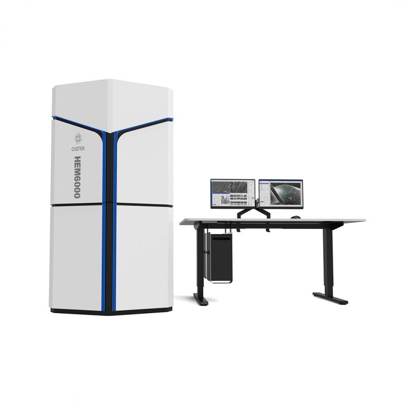
The FE-SEM is capable of producing highly detailed 3D surface structures of solid-state samples. With a scanning transmission detector, it can also reveal internal structures of thin samples. In addition, the built-in high-performance EDS (energy-dispersive X-ray spectroscopy) enables qualitative and semi-quantitative elemental analysis on sample surfaces.
By 2023, their previous SEMs (an environmental SEM and a benchtop SEM) could no longer meet the growing demand for higher resolution and imaging precision. A new FE-SEM became necessary.
“After comprehensive evaluation and expert reviews, CIQTEK SEM5000 Series was selected through a competitive public bidding process,” Dr. Su recalled. “Its technical specifications align with global standards, the extended warranty is reassuring, and the after-sales service has been extremely responsive. After two years of use, we are very satisfied with its truly excellent value.”
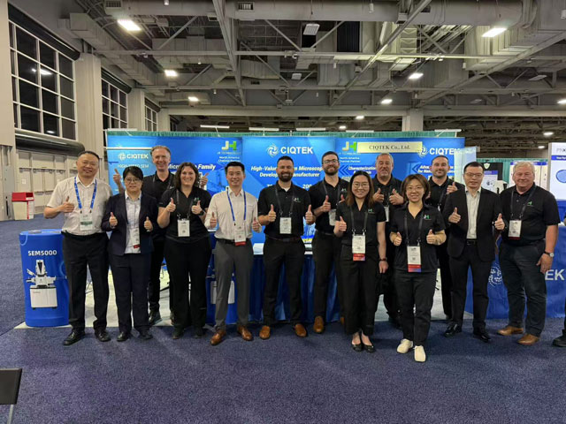
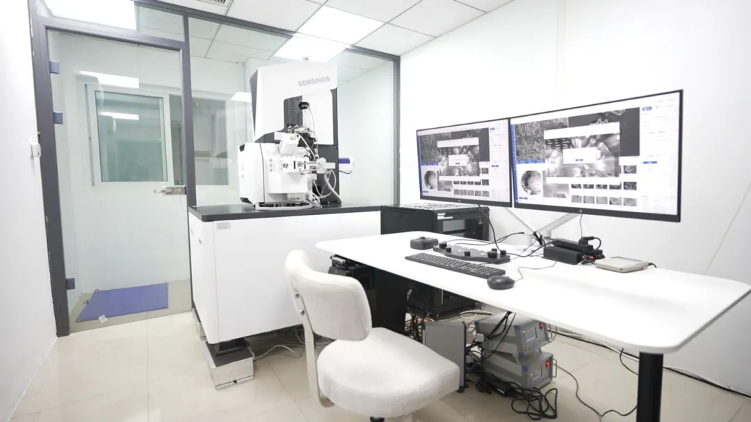 CIQTEK SEM Microscopy at IAE, CAS
Field-Tested Excellence: CIQTEK SEMs Stand Out
Lee Xu, a key operator of the SEM5000 at the institute, is particularly impressed with the CIQTEK SEM5000's performance.
“The SEM5000 allows us to observe a wide variety of biological and material samples at magnifications ranging from 2,000x to 100,000x, and the image quality remains excellent throughout that range,” Lee noted.
One impressive feature is the user-friendly software.
“The interface is intuitive and easy to use. One of my favorite features is automatic brightness and contrast adjustment. It speeds up image acquisition and ensures consistent lighting in captured images.”
The after-sales support stands out.
“CIQTEK’s SEM engineers regularly check in on the instrument status and provide timely maintenance. Any issues we’ve encountered have been resolved quickly and professionally.”
The paired EDS system also performs reliably.
“It enables both qualitative and quantitative analysis of elemental composition on the sample surface. Point analysis is the most commonly used approach, allowing the detection of elements at specific spots or micro-areas, which is ideal for studying localized chemical properties. Line analysis helps map the distribution of selected elements along a defined path, revealing concentration gradients in materials.”
Since its installation, the CIQTEK SEM5000 has played a vital role in the lab’s scientific output.
“Over the past year and a half, we’ve analyzed a large number of biological and material samples,” said Lee. “The data and images generated have been used in theses, publications, and ongoing research.”
Notable Publications Utilizing CIQTEK SEM5000 Data:
-
"Acetochlor accelerates the aging of plastic film microplastics in soil by altering the plastisphere microbiota", published in the Journal of Hazardous Materials.
-
"Four new species of Trichoderma from subtropical forests in Southwest China", published in the Journal of Fungi.
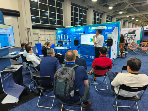
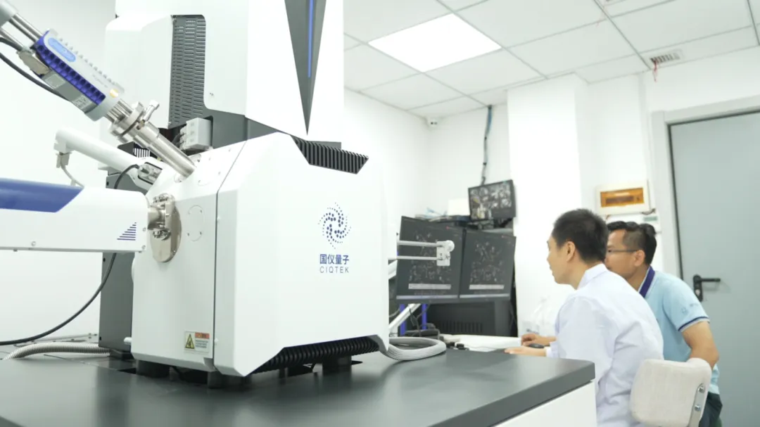 IAE, CAS Team Analyzing with the CIQTEK SEM Microscopy