What Are the Design Considerations for Hybrid High-Frequency PCBs?
What Are the Design Considerations for Hybrid High-Frequency PCBs?
Introduction
Hybrid (mixed dielectric) high-frequency PCBs combine different materials to optimize electrical performance, thermal stability, and manufacturability. These mixed dielectric hybrid boards are widely used in RF/microwave applications, aerospace, radar systems, and telecommunications, where signal integrity and thermal management are critical.
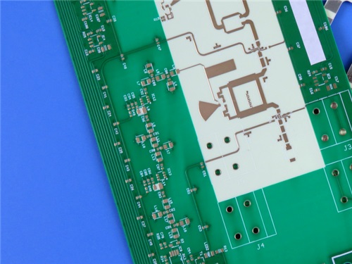
Designing hybrid PCB requires careful consideration of material properties, layer stackup, signal integrity, and manufacturing constraints. In this article, we explore key design considerations and provide practical insights, using a 4-layer hybrid PCB (RO4350B + High-Tg FR-4 S1000-2M) as an example.
1. Material Selection and Compatibility
Key Factors in Material Selection
Dielectric Constant (Dk) & Loss Tangent (Df):
- -High-frequency signals require stable Dk and low-loss materials (e.g., Rogers RO4350B with Dk=3.48, Df=0.0037).
- -FR-4 (S1000-2M) provides mechanical support but has higher loss, so it’s best used in non-critical layers.
Thermal Expansion (CTE) Mismatch:
- -RO4350B has a CTE close to copper (X/Y: 10-12 ppm/°C), reducing warpage and via reliability issues.
- -S1000-2M offers excellent Z-axis CTE for plated through-hole (PTH) reliability.
Thermal Conductivity & Tg:
- -RO4350B has a high Tg (>280°C) and thermal conductivity (0.69 W/m/°K), making it suitable for high-power RF designs.
- -S1000-2M (Tg 180°C) provides mechanical stability and lead-free compatibility.

Example PCB Construction
Our 4-layer hybrid circuit board combines:
Signal Layers (RO4350B): Optimized for RF performance.
Core/Prepreg (FR-4 S1000-2M): Provides structural integrity.
Stackup:
Layer 1 (RF Signal): 35μm Cu + RO4350B (0.254mm)
Layer 2 (Ground/Power): 35μm Cu + Prepreg (0.254mm)
Layer 3 (Inner Signal): 35μm Cu + S1000-2M (0.8mm)
Layer 4 (Bottom Layer): 35μm Cu
2. Signal Integrity and Impedance Control
Critical Design Rules
Controlled Impedance Routing:
- RO4350B’s stable Dk allows precise impedance matching (e.g., 50Ωmicrostrip lines).
- Use field solvers to calculate trace width/spacing (e.g., 4/6 mil traces in our example).
Minimizing Crosstalk & Loss:
- Keep high-speed traces short and avoid sharp bends.
- Use ground planes (Layer 2 in our stackup) to reduce interference.
Via Optimization:
- Our example Hybrid PCB Board PCB uses 0.20mm minimum hole size with 20μm plating thickness for reliability.
- Avoid blind vias to simplify manufacturing (as seen in our design).
3.Thermal Management Considerations
Preventing Delamination & Warpage
- CTE Matching: RO4350B’s low CTE reduces stress between layers.
- Thermal Relief in Pads: Prevents excessive heat during soldering.
Heat Dissipation Strategies
- Copper Weight: Our PCB uses 1oz (35μm) copper for balanced current handling and heat spreading.
- Surface Finish: ENIG (Electroless Nickel Immersion Gold) ensures reliable solderability and corrosion resistance.
4. Manufacturing and Reliability
Fabrication Tolerances
- Board Dimensions: 173mm x 85.3mm (±0.15mm tolerance).
- Solder Mask & Silkscreen: Green solder mask (top/bottom) with white/green silkscreen for component marking.
Quality Assurance
- 100% Electrical Testing: Ensures no short/open circuits before shipment.
- IPC-Class-2 Compliance: Guarantees reliability for commercial applications.
5. Applications of Hybrid High-Frequency PCBs
Our example PCB (RO4350B + S1000-2M) is ideal for:
✅Radar & Guidance Systems (stable Dk, low loss)
✅5G & Millimeter-Wave Antennas (precise impedance control)
✅Aerospace & Defense Electronics (high thermal reliability)
Conclusion
Designing hybrid high-frequency PCBs requires a balance between material properties, signal integrity, and manufacturability. By selecting compatible materials (like RO4350B FR-4 hybrid PCB), optimizing stackup, and following best practices in impedance control and thermal management, engineers can achieve high-performance RF/microwave designs.
Looking for a reliable hybrid PCB supplier? Our 4-layer mixed-dielectric PCB (RO4350B + S1000-2M) meets stringent RF and thermal requirements while ensuring cost-effective production. Contact us today for your high-frequency PCB needs!
