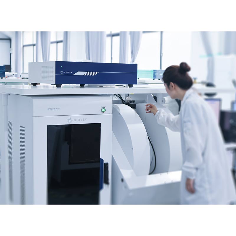
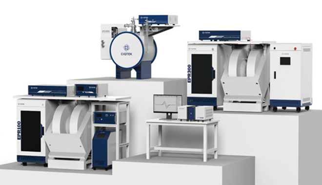
Choosing the right EPR spectrometer in 2025 means more than just comparing specs. With expanding applications in chemistry, materials science, spintronics, and biophysics, labs need to consider long-term usability, performance, upgrade flexibility, and technical support. Whether you're replacing an aging setup or equipping a new facility, this guide walks through key decision points based on real-world needs and lab feedback.


1. Define Your Research and Teaching Priorities

Start with the core question: What will you actually use the EPR system for?

  - Routine CW EPR for free radicals and transition metals?

  - Advanced pulse EPR for spin coherence, relaxation, or DEER?

  - Do undergraduate teaching labs require safe and intuitive operation?

If your lab focuses on education or simpler paramagnetic analysis, a benchtop EPR spectrometer may be sufficient and cost-effective. For groups targeting pulse techniques, variable temperature EPR or time-domain studies, a full console system with pulse modules is essential.

CIQTEK offers both compact EPR spectrometers for academic labs and research-grade advanced EPR solutions ready for pulse and cryogenic experiments, with modular options that support future expansion.


2. Match Technical Specs with Your Use Cases

Before investing, dig into performance indicators that align with your experiments.

  - CW Sensitivity: Look for high signal-to-noise ratio and digital field stability to ensure reproducibility in long scans.

  - Pulse Capabilities: Evaluate whether you’ll need phase-coherent pulse programming, arbitrary waveform generation, or echo detection.

  - VT Control: Labs operating below 77 K require seamless switching between nitrogen and helium, with minimal manual tuning.

  - Frequency Band: X-band EPR is the standard, but applications in low- or high-frequency may call for dual-band flexibility.

Real feedback from CIQTEK EPR users in Europe, the U.S.,  China, Japan, etc, shows that digital upgrades to control modules and built-in VT systems have cut down tuning time and improved overall workflow stability—especially in multi-user environments.


3. Consider Footprint, Infrastructure, and Software Usability

A common limitation in university and shared labs is space. A benchtop EPR can fit into small teaching or departmental rooms with limited cooling and power supply. These systems are also easier to relocate or share.

In contrast, full-size EPR spectrometers need dedicated space, often including external chillers or helium recovery if used at low temperature. But they offer broader accessory compatibility, like resonators, cryostats, and future pulse upgrades.

Also, test the software: modern EPR software should support automated tuning, graphical pulse design, and batch data export. CIQTEK’s unified control interface allows both beginners and advanced users to run experiments efficiently, reducing training time for new researchers.


4. Think Long-Term: Service, Upgrade Paths, and Support

Installation is only the beginning. A reliable support model ensures you can maximize performance in the long run.

  - Does the vendor offer remote diagnostics?

  - Are software and firmware updates included?

  - Is there local service coverage or a regional demo lab?

CIQTEK works with local partners and academic labs across Europe and North America. Several customers highlight the responsiveness of their engineering team and the clarity of their training materials. The company also provides EPR modernization and upgrade services, helping labs upgrade legacy magnets with new digital control, VT integration, and pulse options without a full system replacement.


5. Learn from Real-World Examples

A materials research group in Asia was able to transform their 20-year-old EPR system into a modern pulse-capable instrument by upgrading with the CIQTEK EPR modernization package. This allowed them to keep using their existing magnet while gaining modern features like programmable pulse sequences and variable temperature control.

Meanwhile, a university in France deployed a CIQTEK benchtop EPR spectrometer for undergraduate education. Faculty reported that the system’s small size, easy calibration, and built-in safety controls made it ideal for hands-on teaching in chemical physics courses.

These examples show how flexible options, from compact teaching units to full lab retrofits, can match different research and budget needs.
 

6. Use This Checklist Before Buying

  - Before making a final decision, go through this checklist:

  - What are your core experimental needs, CW, pulse, VT, or all?

  - Do you need benchtop flexibility or full-featured performance?

  - How much space and power is available in your lab?

  - Is the software easy enough for students or first-time users?

  - Are upgrade paths available for future Pulse or VT modules?

  - Can you request a demo, on-site or remote, with sample testing?

  - What’s the total cost of ownership over 5–10 years, including service?


CIQTEK: A Flexible Choice for Modern Labs

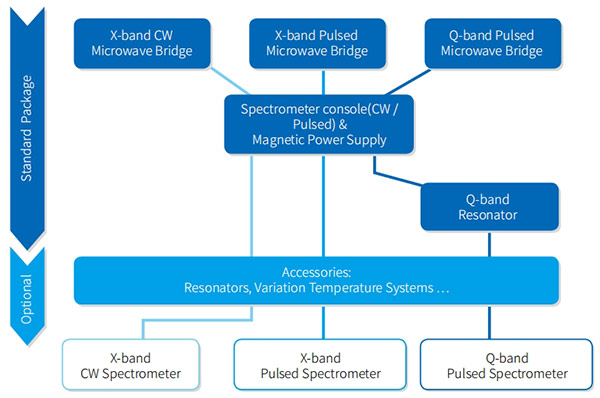
Whether you're setting up a teaching lab, replacing an aging system, or expanding into pulse EPR research, CIQTEK EPR solutions are designed to grow with your lab. Compact systems offer excellent entry points for education, while console platforms provide advanced research functionality and seamless integration with variable temperature and pulse upgrades. With real-world modernization services and local support options, CIQTEK enables labs to move forward with confidence, without overcommitting budget or lab space.

Learn more about CIQTEK EPR products and modernization services at www.ciqtekglobal.com

CIQTEK

The Z178 Smart Watch redefines what a wearable device can do, blending style and functionality into one sleek package. With its stunning HD Retina display and IP68 waterproof rating, this watch is built to keep up with your active lifestyle while maintaining a premium look. Whether you're swimming, running, or attending a business meeting, the Z178 adapts effortlessly to your needs while providing crystal-clear visibility in any lighting condition.


Beyond its elegant design, the Z178 excels in keeping you connected and healthy. The built-in Bluetooth calling feature allows you to take calls directly from your wrist, while real-time notifications ensure you never miss important messages. Fitness enthusiasts will appreciate the 123+ sports modes and advanced tracking capabilities that monitor everything from steps to calories burned. The watch even reminds you to stay hydrated, making it a true wellness partner that cares about your daily habits.


What truly sets the Z178 apart is its ability to match your personal style. With hundreds of customizable watch faces, you can switch between sporty, classic, or modern designs to suit any occasion. Combined with long battery life and durable construction, this smartwatch is more than just a gadget—it's a reliable companion for every adventure. Whether you're exploring the outdoors or navigating a busy workday, the Z178 is designed to enhance your life with smart technology and timeless style.


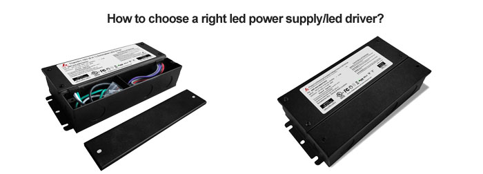
According to the usage, determine the required output voltage and current; the size of the power supply, the installation method and the installation hole location; there are several outputs, whether each output needs to be electrically isolated; the input voltage range; according to the ambient temperature, determine the drop The amount of power, the power of the power supply; whether certification and safety standards are required; the cooling method of the power supply: natural cooling or forced air cooling; electromagnetic compatibility standards.

1. Select the required safety regulations and electromagnetic compatibility (EMC) certification.

2. Try to use the standard power supply of the power adapter manufacturer, including the standard size and output voltage. In this way, the delivery time is relatively fast; on the contrary, the special size and output voltage will extend the delivery time and increase the cost.

3. In addition, it is necessary to consider the working environment temperature of the power supply, and whether there is additional auxiliary heat dissipation equipment, and the power supply needs to be derated in the excessively high ambient temperature power supply. Refer to the derating curve of ambient temperature to output power.

4. Select the appropriate input voltage range. Taking AC input as an example, the commonly used input voltage specifications are 110V, 220V, so there are correspondingly three specifications of 110V, 220V AC switching, and universal input voltage (AC: 100V-265V). The input voltage specification should be selected according to the area of use.

power supply

5. Choose the right power. The switching power supply consumes a part of the power during operation and releases it in the form of heat. In order to increase the life of the power supply, it is recommended to choose a model with a 30% more output power rating.

Across chemistry and materials science labs, EPR spectrometers have powered research for decades. But as experimental needs advance, many facilities are facing the same question: When is it time to modernize your EPR system?

Instead of costly full replacements, more labs are turning to targeted modernization to bring aging EPR equipment up to current research standards while maximizing existing hardware investment.


The Hidden Cost of Outdated EPR Instruments

Many EPR spectrometers installed in the 1990s or early 2000s still function for basic CW measurements. However, as field stability weakens, control electronics degrade, and cryogenic components age, research capabilities gradually decline.

A materials group in Germany recently struggled to maintain pulse stability on their 20-year-old system while expanding into low-temperature spin dynamics. With spare parts becoming scarce, their system downtime was increasing.

Similar challenges appear in US chemistry departments, where outdated control software makes EPR training unnecessarily complex for graduate students. Some labs operate systems that only a few technicians can run reliably.


What EPR Modernization Really Delivers

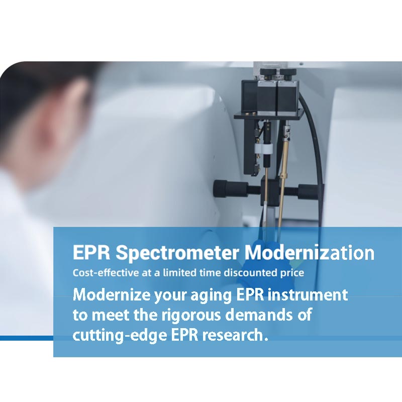
Modernizing an EPR system allows labs to extend instrument lifetime and add advanced functionality significantly. Instead of replacing entire magnets or RF hardware, EPR modernization and upgrades focus on:

 - Digital control electronics with improved field precision

 - Pulse EPR capability with modern phase coherence and timing resolution

 - Seamless integration of nitrogen and helium cryostat systems for variable temperature studies

 - Fully digital software interfaces that simplify both teaching and advanced research

This approach preserves valuable core components while dramatically expanding experimental capability.


Real-World Case: Advanced Materials Research Enabled by EPR Modernization

At a leading national laboratory in China, a research team studying spin defects and paramagnetic centers encountered serious limitations with their legacy EPR system. Their older EPR spectrometer lacked the phase stability and pulse flexibility required for precise coherence and relaxation measurements. After a full digital control and pulse module upgrade delivered by CIQTEK, the lab successfully expanded into advanced pulse EPR experiments while preserving its existing hardware setup. 

Similar modernization projects have been successfully completed at several European research institutes, supporting new work in catalysis, spintronics, and materials characterization.


Why CIQTEK Modernization and Upgrade Is Gaining Momentum Worldwide

Full EPR system replacement can be financially challenging and logistically disruptive. CIQTEK EPR modernization services offer a highly cost-effective alternative by:

 - Extending instrument life by 10 years or more

 - Providing cutting-edge pulse and VT functionality

 - Lowering training barriers with intuitive, modern software

 - Minimizing lab downtime during transition

Importantly, CIQTEK supports EPR modernization and upgrade services with comprehensive local service support worldwide, complemented by expert application training and rapid remote diagnostics to minimize research interruptions.


CIQTEK EPR Modernization: Upgrade Smarter, Not Harder

Whether your lab needs:

 - Full digital control upgrades

 - Pulse EPR expansion modules

 - Variable temperature system integration

 - Modern teaching software platforms

CIQTEK delivers proven EPR modernization and upgrade solutions already operating in labs worldwide.


If your existing EPR system is limiting your research, CIQTEK EPR modernization can unlock new capabilities while protecting your hardware investment.

>> Learn more or schedule a technical consultation now.

CIQTEK Modernization and Upgrade

How to Choose Between RO4350B, PTFE, and Ceramic-Filled Substrates?


Introduction

High-frequency PCBs are critical in modern RF and microwave applications, including 5G communications, radar systems, and satellite technology. Selecting the right substrate material is essential to ensure signal integrity, thermal stability, and manufacturability. Three of the most commonly used high-frequency PCB materials are Rogers RO4350B, PTFE (Teflon), and ceramic-filled laminates.


In this guide, we’ll explore the properties, advantages, and trade-offs of each material and provide insights on how to choose the best option for your application. We’ll also showcase a real-world6-layer RF PCB example using RO4350B and RO4450F bondply to illustrate material selection in practice.


Key Considerations for High-Frequency PCB Materials

Before diving into material specifics, let’s outline the key factors that influence substrate selection:


  • -Dielectric Constant (Dk)–Affects signal propagation speed and impedance control.
  • -Dissipation Factor (Df)–Determines signal loss at high frequencies.
  • -Thermal Conductivity–Important for heat dissipation in power applications.
  • -Coefficient of Thermal Expansion (CTE)–Impacts reliability under thermal cycling.
  • -Manufacturability–Some materials require specialized processing.
  • -Cost- High-performance materials can be expensive.


Now, let’s compare the three leading high-frequency PCB materials.


1. RO4350B: The Cost-Effective High-Performance Option

Rogers 4350B is a woven glass-reinforced hydrocarbon/ceramic laminate that offers a balance between electrical performance and ease of fabrication.


Key Features of RO4350B


  • -Dielectric Constant (Dk): 3.48±0.05 @ 10 GHz
  • -Dissipation Factor (Df): 0.0037 @ 10 GHz (low loss)
  • -Thermal Conductivity: 0.69 W/m/°K (better than FR4)
  • -CTE: Low expansion (X/Y: 10-12 ppm/°C, Z: 32 ppm/°C)
  • -Tg (Glass Transition Temp): >280°C (excellent thermal stability)
  • -Moisture Absorption: 0.06% (minimal impact on performance)


Why Choose RO4350B?

✔Cost-Effective Alternative to PTFE–RO4350B performs close to PTFE but at a lower cost.

✔Compatible with Standard FR4 Processes–No special drilling or plating required.

✔Stable Dk Over Frequency & Temperature–Ideal for RF and microwave circuits.


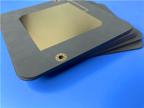
6-Layer RO4350B PCB 1.8mm Thick


Example: 6-Layer RF PCB Using RO4350B

Here’s a real-world PCB we manufactured using RO4350B cores and RO4450F bondply:


Layer Count: 6

Dimensions: 98.5 mm×68 mm (±0.15mm)

Min Trace/Space: 4/6 mils

Min Hole Size: 0.3mm

Blind Vias: L1-L2, L3-L6, L5-L6

Board Thickness: 1.8mm

Surface Finish: Immersion Gold

Solder Mask: Green (top & bottom)

Quality Standard: IPC-Class-2


Stackup Structure:


Top Layer (35µm Cu)

RO4350B Core (0.254mm)

Inner Layer (35µm Cu)

RO4450F Bondply (4mil, 2x)

RO4350B Core (0.762mm)

Bottom Layer (35µm Cu)


This design is optimized for RF applications with controlled impedance and low insertion loss.


2. PTFE (Teflon): The Ultra-Low Loss Solution

PTFE (Polytetrafluoroethylene) is the gold standard forultra-high-frequency PCBs due to its extremely low loss.


Key Features of PTFE


  • Dk: 2.1–3.5 (varies with filler material)
  • Df: As low as 0.0009 (best for mmWave applications)
  • Thermal Stability: Excellent, but high CTE (~160 ppm/°C)
  • Challenges: Requires specialized drilling/plating processes.


When to Use PTFE?

✔Millimeter-Wave (mmWave) Circuits (24GHz+, 5G, radar)

✔Extremely Low-Loss Applications (satellite comms, aerospace)

✖Not Ideal for Cost-Sensitive Projects (higher fabrication costs)


3. Ceramic-Filled Materials: High Thermal & Mechanical Stability

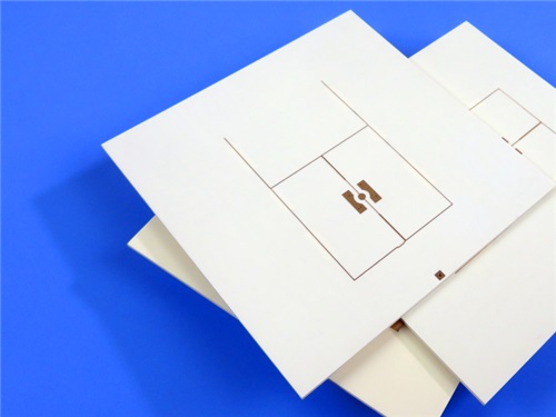
Ceramic-filled substrates (e.g.,Rogers RO3000 series) offer enhanced thermal conductivity and mechanical strength.


Key Features of Ceramic-Filled Laminates


  • Dk: 3.0–10.2 (adjustable based on ceramic content)
  • Df: 0.001–0.003 (low loss, but not as good as PTFE)
  • Thermal Conductivity: Up to 4 W/m/°K (great for power amplifiers)
  • CTE: Matches copper (~17 ppm/°C), reducing warping risks.


Best Applications for Ceramic-Filled PCBs

✔High-Power RF Devices (base stations, power amplifiers)

✔Applications Needing Heat Dissipation (automotive radar, LED PCBs)


Material Selection Guide: RO4350B vs. PTFE vs. Ceramic


Parameter

RO4350B

PTFE

Ceramic-Filled

Dk (10 GHz)

3.48 ±0.05

2.1–3.5

3.0–10.2

Df (10 GHz)

0.0037

0.0009–0.002

0.001–0.003

Thermal Conductivity

0.69 W/m/°K

Low (~0.2)

Up to 4 W/m/°K

CTE (ppm/°C)

X/Y: 10-12, Z: 32

~160 (high)

~17 (matches Cu)

Cost

Medium

High

Medium-High

Manufacturing Ease

Easy (FR4-like)

Difficult (special processes)

Moderate


Which One Should You Choose?


  • For most RF applications (up to 20GHz), RO4350B Frequency PCB is the best balance of cost and performance.
  • For mmWave (24GHz+), PTFE is ideal but expensive.
  • For high-power/high-thermal applications, ceramic-filled laminates are superior.


Conclusion

Selecting the right high-frequency PCB material depends on your application’s frequency range, thermal requirements, and budget.

RO4350B PCB is the best all-around choice for most RF designs, offering low loss, stable Dk, and easy fabrication.


PTFE is unmatched for ultra-low-loss mmWave circuits but comes at a higher cost.


Ceramic-filled materials excel in high-power and high-thermal scenarios.


Our 6-layer RF PCB example demonstrates howRogers4350B and RO4450F bondply can be used effectively in real-world designs. If you need high-frequency PCBs with optimized material selection, we provide global manufacturing with IPC-Class-2 quality standards.


Need a custom RF PCB solution? Contact us today for expert guidance!


PTFE Materials Are Difficult to Process—How to Solve Lamination and Drilling Challenges?


Introduction

Polytetrafluoroethylene (PTFE), commonly known by the brand name Teflon (TFE), is a high-performance material widely used in printed circuit boards (PCBs) for high-frequency applications. Its low dielectric constant (Dk) and dissipation factor (Df) make it ideal for RF, microwave, and millimeter-wave circuits. However, TFE materials like Rogers RT/duroid 5880 present significant challenges in lamination and drilling due to their unique properties.


In this article, we’ll explore the key difficulties in TFE material PCB fabrication and provide practical solutions to overcome them. We’ll also highlight how our 3-layer rigid PCB with RTduroid 5880 and RO4450F bonding ply successfully addresses these challenges while maintaining high-frequency performance.


Why TFE Materials Are Difficult to Process

PTFE-based laminates like RT/duroid 5880 offer outstanding electrical properties, including:


  • -Low dielectric constant (Dk = 2.2±0.02)
  • -Ultra-low dissipation factor (Df = 0.0009 at 10 GHz)
  • -Excellent thermal stability


However, these benefits come with manufacturing challenges:


1. Lamination Difficulties


  • -Poor Adhesion: PTFE is inherently non-sticky, making it difficult to bond with copper layers.
  • -Thermal Expansion Mismatch: PTFE has a higher coefficient of thermal expansion (CTE) than copper, leading to potential delamination.
  • -Resin Flow Control: Excessive heat and pressure can cause resin squeeze-out, affecting dielectric thickness.


2. Drilling Challenges


  • -Material Softness: PTFE is soft and prone to smearing during drilling, leading to poor via quality.
  • -Thermal Sensitivity:Excessive heat from drilling can degrade PTFE’s electrical properties.
  • -Hole Wall Roughness: Improper drilling can result in rough via walls, affecting signal integrity.


RTduroid 5880 PCB 3-layer 3.3mm Thick Immersion Gold


Solutions for Successful TFE PCB Fabrication


1. Optimizing Lamination for TFE Materials

a) Use Special Bonding Materials

To improve adhesion, we use RO4450F bonding ply—a thermoset material compatible withPTFE laminates. In our 3-layer PCB stackup, RO4450F ensures strong interlayer bonding while maintaining electrical performance.


Our PCB Stackup Example:


Layer 1: Copper (35μm)

Core: RT/duroid 5880 (1.575 mm)

Layer 2: Copper (35μm)

Bonding Ply: RO4450F (0.102 mm)

Core: RT/duroid 5880 (1.575 mm)

Layer 3: Copper (35μm)


b) Controlled Lamination Parameters


  • Temperature & Pressure: Precise control prevents resin flow issues and maintains consistent dielectric thickness.
  • Slow Ramp-Up Rates: Gradual heating minimizes thermal stress, reducing delamination risks.


2. Overcoming Drilling Challenges

a) Specialized Drill Bits & Parameters


  • Carbide Drill Bits: Harder than standard drills, reducing PTFE smearing.
  • Optimized RPM & Feed Rate: Prevents excessive heat buildup.


b) Laser Drilling for Micro-Vias


  • For smaller holes (0.4mm in our PCB), laser drilling provides cleaner, more precise vias with minimal wall roughness.


c) Post-Drilling Treatments


  • Plasma Etching: Removes PTFE residue from via walls.
  • Via Plating (20μm in our PCB): Ensures reliable electrical connections.


Case Study: Our 3-Layer RT/duroid 5880 PCB

To demonstrate successful TFE material processing, here’s a breakdown of our high-frequency PCB solution:


Key Specifications:

Material: RT/duroid 5880 (core) + RO4450F (bonding ply)

Layers: 3

Board Thickness: 3.3 mm

Min Trace/Space: 5/7 mils

Min Hole Size: 0.4 mm

Via Plating Thickness: 20μm

Surface Finish: Immersion Gold (enhances signal integrity)


Why This Design Works for High-Frequency Applications?

✔Low Signal Loss: RT/duroid 5880’s ultra-low Df ensures minimal RF attenuation.

✔Stable Dk: Uniform dielectric constant across frequencies.

✔Robust Construction: RO4450F bonding ply prevents delamination.

✔Precision Drilling: 0.4mm vias with 20μm plating ensure reliable interconnects.


Conclusion: Partner with a PCB Supplier Experienced in TFE Materials

Fabricating High Frequency PTFE PCB with RT/duroid 5880 and other PTFE-based materials requires specialized expertise in lamination, drilling, and thermal management. By optimizing bonding materials, drilling techniques, and lamination processes, we deliver high-performance PCBs for RF, aerospace, and millimeter-wave applications.


Looking for a reliable TFE PCB supplier? Our 3 Layer High Frequency PCB RT/duroid 5880 is IPC-Class-2 compliant, electrically tested, and available worldwide. Contact us today for high-frequency PCB solutions tailored to your needs!


What Are the Design Considerations for Hybrid High-Frequency PCBs?


Introduction

Hybrid (mixed dielectric) high-frequency PCBs combine different materials to optimize electrical performance, thermal stability, and manufacturability. These mixed dielectric hybrid boards are widely used in RF/microwave applications, aerospace, radar systems, and telecommunications, where signal integrity and thermal management are critical.


Designing hybrid PCB requires careful consideration of material properties, layer stackup, signal integrity, and manufacturing constraints. In this article, we explore key design considerations and provide practical insights, using a 4-layer hybrid PCB (RO4350B + High-Tg FR-4 S1000-2M) as an example.


1. Material Selection and Compatibility

Key Factors in Material Selection


Dielectric Constant (Dk) & Loss Tangent (Df):


  • -High-frequency signals require stable Dk and low-loss materials (e.g., Rogers RO4350B with Dk=3.48, Df=0.0037).
  • -FR-4 (S1000-2M) provides mechanical support but has higher loss, so it’s best used in non-critical layers.


Thermal Expansion (CTE) Mismatch:


  • -RO4350B has a CTE close to copper (X/Y: 10-12 ppm/°C), reducing warpage and via reliability issues.
  • -S1000-2M offers excellent Z-axis CTE for plated through-hole (PTH) reliability.


Thermal Conductivity & Tg:


  • -RO4350B has a high Tg (>280°C) and thermal conductivity (0.69 W/m/°K), making it suitable for high-power RF designs.
  • -S1000-2M (Tg 180°C) provides mechanical stability and lead-free compatibility.


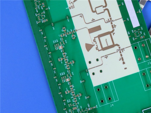
4-Layer Hybrid PCB 10mil RO4350B and High Tg FR-4


Example PCB Construction

Our 4-layer hybrid circuit board combines:


Signal Layers (RO4350B): Optimized for RF performance.

Core/Prepreg (FR-4 S1000-2M): Provides structural integrity.


Stackup:

Layer 1 (RF Signal): 35μm Cu + RO4350B (0.254mm)

Layer 2 (Ground/Power): 35μm Cu + Prepreg (0.254mm)

Layer 3 (Inner Signal): 35μm Cu + S1000-2M (0.8mm)

Layer 4 (Bottom Layer): 35μm Cu


2. Signal Integrity and Impedance Control

Critical Design Rules


Controlled Impedance Routing:


  • RO4350B’s stable Dk allows precise impedance matching (e.g., 50Ωmicrostrip lines).
  • Use field solvers to calculate trace width/spacing (e.g., 4/6 mil traces in our example).


Minimizing Crosstalk & Loss:


  • Keep high-speed traces short and avoid sharp bends.
  • Use ground planes (Layer 2 in our stackup) to reduce interference.


Via Optimization:


  • Our example Hybrid PCB Board PCB uses 0.20mm minimum hole size with 20μm plating thickness for reliability.
  • Avoid blind vias to simplify manufacturing (as seen in our design).


3.Thermal Management Considerations


Preventing Delamination & Warpage


  • CTE Matching: RO4350B’s low CTE reduces stress between layers.
  • Thermal Relief in Pads: Prevents excessive heat during soldering.


Heat Dissipation Strategies


  • Copper Weight: Our PCB uses 1oz (35μm) copper for balanced current handling and heat spreading.
  • Surface Finish: ENIG (Electroless Nickel Immersion Gold) ensures reliable solderability and corrosion resistance.


4. Manufacturing and Reliability

Fabrication Tolerances


  • Board Dimensions: 173mm x 85.3mm (±0.15mm tolerance).
  • Solder Mask & Silkscreen: Green solder mask (top/bottom) with white/green silkscreen for component marking.


Quality Assurance


  • 100% Electrical Testing: Ensures no short/open circuits before shipment.
  • IPC-Class-2 Compliance: Guarantees reliability for commercial applications.


5. Applications of Hybrid High-Frequency PCBs

Our example PCB (RO4350B + S1000-2M) is ideal for:

✅Radar & Guidance Systems (stable Dk, low loss)

✅5G & Millimeter-Wave Antennas (precise impedance control)

✅Aerospace & Defense Electronics (high thermal reliability)


Conclusion

Designing hybrid high-frequency PCBs requires a balance between material properties, signal integrity, and manufacturability. By selecting compatible materials (like RO4350B FR-4 hybrid PCB), optimizing stackup, and following best practices in impedance control and thermal management, engineers can achieve high-performance RF/microwave designs.


Looking for a reliable hybrid PCB supplier? Our 4-layer mixed-dielectric PCB (RO4350B + S1000-2M) meets stringent RF and thermal requirements while ensuring cost-effective production. Contact us today for your high-frequency PCB needs!


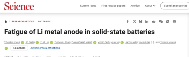
Recently, the top international academic journal "Science" published a research paper titled "Fatigue of Li metal anode in solid-state batteries" by Professor Wei Luo from Tongji University, along with Professor Yunhui Huang from Huazhong University of Science and Technology and other collaborators.


This study revealed for the first time the fatigue failure phenomenon of the lithium metal anode in solid-state batteries, unveiled a new fatigue failure mechanism, and proposed novel strategies to inhibit fatigue failure and enhance the performance of solid-state batteries.


In this research, the team utilized the Tungsten Filament SEM from CIQTEK for in-situ SEM fatigue testing and obtained excellent test results.


Link to the original paper:

https://www.science.org/doi/10.1126/science.adq6807


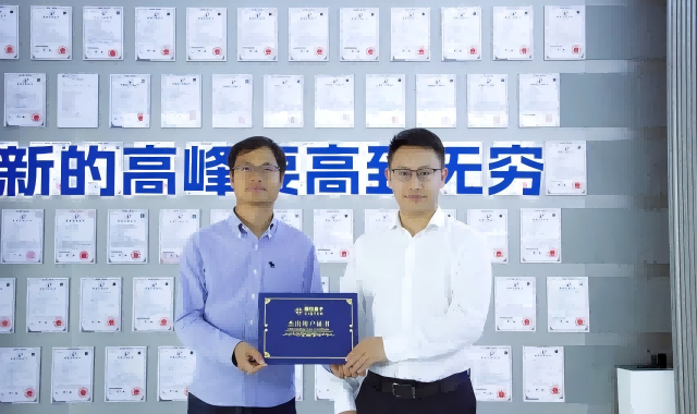
Recently, the first author of this paper, Professor Bo Chen from Tongji University, was invited to visit CIQTEK and granted an interview with us.


Professor Bo Chen introduces: "Our research group mainly focuses on two aspects, one being imaging with synchrotron X-rays, and the other involving electron microscopy imaging, as with CIQTEK. The work of our entire research group revolves around the nano- and micro-structures of materials, particularly in the three-dimensional nano- and micro-structures of materials. Therefore, our entire research group can be referred to as the materials nano- and micro-structure research group."


Regarding the paper recently published in "Science," Professor Bo Chen stated: "The paper seized upon a phenomenon that hadn't been extensively considered before, which is the fatigue of lithium metal. Previously, everyone believed that it was electrochemical fatigue generated during charging and discharging processes, but in reality, it also exhibits mechanical fatigue during these processes."


"The primary discovery of this research is that lithium exhibits not only electrochemical fatigue during charging and discharging but also mechanical fatigue manifested during these processes, which combined are the main causes of destruction in the lithium metal of solid-state batteries. The paper further suggests that by alloying lithium metal to enhance its physical properties, the lifespan of solid-state batteries can be improved. This is a groundbreaking finding and quite intriguing."


When designing experiments, the team observed both types of fatigue by installing fatigue devices on the electron microscope. Since the research group only had one electron microscope, in order to comprehensively observe, they used an in-situ tensile stage developed by Professor Jixue Li at Hangzhou Yuanwei Technology Company. Professor Bo Chen said, "With the help of Professor Li, we jointly created a fatigue tensile-testing device. The mechanical fatigue experiment of lithium metal was conducted by Professor Li using the electron microscope from CIQTEK for in-situ tensile testing."


When asked about his views on CIQTEK Electron Microscopes, Professor Bo Chen was very candid and sincere: "For us, our only requirement is that the equipment must perform well."


As a research scientist who enjoys hands-on exploration, Professor Bo Chen also shared some personal insights on using CIQTEK instruments. He mentioned that when the instrument offers both quality and cost-effectiveness, it greatly enhances the interest of researchers in tinkering with the machine, reduces the sense of alienation towards expensive instruments, and encourages researchers to utilize the machine more effectively, thereby unleashing more research creativity.


Ending with Professor Bo Chen's words, CIQTEK will continue to stick to the slogan: Successful Customers, Successful Companions!

If you love Garmin’s rugged durability but not its premium price tag, meet the DA03 Smartwatch—a feature-packed rival that delivers military-grade toughness at a fraction of the cost.


While Garmin dominates the adventure watch market, the North Edge DA03 matches its resilience with dust-proof, antifreeze, and high-temperature resistance—perfect for hikers, cyclists, and outdoor enthusiasts. With dust-proof, antifreeze, and high-temperature resistance, the DA03 is built for adventurers. Its Bluetooth call quality rivals high level watch, thanks to high-fidelity waterproof speakers—perfect for workouts or rainy days. Health tracking is another standout, with heart rate, blood oxygen, and sleep monitoring comparable to Fitbit. Plus, customizable watch faces let you switch between sporty and sleek looks effortlessly.


If you want Garmin’s toughness and Fitbit’s health tracking—without the premium cost, the DA03 is your best bet. Ready to upgrade? This might just be your next favorite smartwatch.


The North Edge manufactual smart watch, outdoor watch, GPS watch etc, welcome to choose us.

smart watch north edge watch


Choosing the right EPR spectrometer for university labs can significantly impact how your team teaches, researches, and collaborates. Whether you're building a new EPR spectroscopy facility or upgrading an aging setup, one key question often comes first: benchtop EPR or full-size EPR?

Both options offer unique strengths, and your decision should depend on factors such as space, research priorities, budget, and the expected user experience. Across Europe, lab choices are shaping a new generation of academic EPR spectroscopy.


Teaching Labs: Why a Benchtop EPR System is Often the Smarter Choice

For chemistry departments and physics teaching labs, especially those focused on undergraduate or master's-level instruction, a full-size spectrometer can be excessive in terms of size, cost, and complexity. More and more institutions are turning to benchtop EPR systems that prioritize accessibility, affordability, and ease of use.

At the National University of Singapore (NUS), CIQTEK Benchtop EPR spectrometer has been integrated into their teaching and demonstration platform for students in the Department of Chemistry. According to faculty feedback, the system enables students to gain hands-on experience with real electron paramagnetic resonance techniques in a compact, classroom-friendly setup. With its small footprint, intuitive software, and reliable performance, it bridges the gap between theoretical instruction and real-world application.

For labs seeking the best benchtop EPR for university education, CIQTEK’s EPR solution stands out with true X-band performance, minimal maintenance needs, and seamless integration into existing teaching modules.


CIQTEK Benchtop EPR200M Spectrometer at the Universiteit Utrecht, Netherlands 

CIQTEK Benchtop EPR200M Spectrometer at the Universiteit Utrecht, Netherlands


Research Labs: Why Full-Size EPR Still Matters for Advanced Science

For advanced research in quantum materials, molecular magnetism, or X-band pulse EPR, the flexibility and sensitivity of a full-size EPR spectrometer remain crucial. These systems offer broader modulation capabilities, stronger field homogeneity, and support for features like variable temperature EPR spectroscopy.

In 2024, a leading UK materials lab upgraded to a CIQTEK CW EPR spectrometer with integrated VT control, specifically to explore spin dynamics in transition metal complexes. The built-in support for nitrogen and helium cryostats allowed the group to run low-temperature experiments (down to 4 K) without external cooling equipment or extended tuning time.

Meanwhile, a German spin physics group working on magnetic nanoparticles adopted a CIQTEK pulse EPR system. Researchers highlighted its clean echo-detected response and its easy automation, ideal for labs needing repeatable and high-throughput EPR experiments.

If your academic team conducts electron paramagnetic resonance at variable temperatures or uses pulse sequences, a full-size model may be a better long-term investment.

CIQTEK X-band EPR Spectrometer

Budget, Space, and Support: What Often Decides the Winner

For many universities, space constraints and budget ceilings make benchtop models attractive. A compact EPR spectrometer helps reduce installation costs and simplifies user training. But it’s not just about equipment, it’s also about support.

CIQTEK has built a strong reputation across Europe for offering fast-response remote diagnostics, local service teams, and multiple demo centers where customers can test instruments before purchase. A lab in Romania that previously struggled with service delays from another vendor saw a dramatic improvement after switching to a CIQTEK EPR system, citing quick turnaround for both questions and maintenance.


CIQTEK EPR Solutions: Designed for Real University Labs

Whether you're a teaching lab looking for an affordable benchtop EPR system or a research group needing X-band pulse EPR with low-temperature cryogenic options, CIQTEK provides tools designed with academic users in mind:

  • - Benchtop EPR: Desktop-sized, user-friendly, reliable. Ideal for chemistry and biology teaching labs.
  • - CW EPR with VT: Built-in support for cryostats, smooth control from 4 K to 300 K. No extra setup needed.
  • - Pulse EPR systems: High SNR, automated sequences, ready for advanced materials research.
  • If your university is exploring the best EPR spectroscopy equipment for 2025, take a closer look at CIQTEK’s growing presence in labs across the U.S., UK, Germany, France, Romania, Netherlands, and beyond.
  •  
  • CIQTEK EPR Spectrometers
  •  

Learn more or request a live demo at https://www.ciqtekglobal.com