RF over Fiber (RFoF) provides an effective way to transport radio frequency signals between physically separated locations. It is widely used in remote antenna systems, satellite ground stations, distributed antenna systems (DAS), broadcast networks, and RF testing environments where long coaxial cable runs can introduce excessive signal loss or installation complexity.
However, choosing the right RFoF solution involves more than checking its frequency range.
Two RF over fiber links may both support 5 MHz to 6 GHz, yet differ significantly in RF input handling, noise performance, gain control, optical configuration, and installation requirements. A link that works well for a fixed point-to-point connection may not be the best choice for an unattended remote site or an embedded RF system.
This guide explains how to evaluate RF over fiber requirements, understand the key specifications, and select the appropriate RFoF architecture for your application.
1. Start With Your RF Signal Requirements
The first step in selecting an RFoF link is understanding the signal that needs to be transported.
An analog RFoF system converts the incoming RF waveform into an optical signal at the transmitter and reconstructs it at the receiver. Unlike digital fiber networking, it does not need to convert the RF signal into Ethernet packets before transmission.
This allows RFoF to transport suitable RF waveforms while preserving their modulation characteristics, provided the complete link meets the required signal-quality specifications.
Before comparing products, identify four essential parameters.
Operating Frequency
Confirm the complete frequency range of the intended signal, including its occupied bandwidth.
For example, an application operating at a 2.4 GHz carrier frequency may require only a relatively narrow RF passband, while a broadband monitoring system may need to handle signals across several gigahertz.
Both applications could use a 5 MHz–6 GHz RFoF link, but their requirements for gain flatness, dynamic range, and signal integrity may differ considerably.
The specified RFoF frequency range must cover the actual RF or IF signal presented to the transmitter. Signals above 6 GHz require appropriate frequency conversion before entering a link limited to 6 GHz.
Signal Format
Identify whether the system carries continuous-wave signals, analog modulation, digitally modulated RF carriers, or multiple simultaneous signals.
For digitally modulated RF transmission, the optical link must maintain sufficient signal quality for the intended modulation scheme.
It is important to distinguish digitally modulated RF from digital data transmission. An RFoF link transports the RF waveform itself; it is not an Ethernet media converter.
RF Input Power
Determine the minimum, typical, and maximum RF power expected at the optical transmitter's RF input.
This is particularly important when the system handles variable signal levels, multiple carriers, or signals arriving from remote antennas.
An unsuitable input level can lead to insufficient output power, poor signal-to-noise ratio, or distortion caused by compression.
Required RF Output Power
Consider the input sensitivity and power requirements of the equipment connected to the RFoF receiver.
A link with higher gain is not automatically better. Excessive gain may overload downstream equipment, while insufficient gain may require additional amplification.
The objective is to achieve the required output level while maintaining adequate noise and linearity margins.
2. Understand the Specifications That Affect RFoF Performance
Once the basic RF requirements are defined, several technical parameters determine whether a particular link can deliver acceptable performance.
Link Gain and Gain Flatness
Link gain describes the difference between the RF input and output power under specified operating conditions.
For a simplified nominal calculation:
RF Output Power (dBm) ≈ RF Input Power (dBm) + Link Gain (dB)
For example, a −30 dBm input entering a nominal 20 dB gain link would produce approximately −10 dBm at the output under its specified reference conditions.
Actual performance depends on frequency, optical path loss, gain variation, and other operating conditions.
Gain flatness describes how consistently the link maintains its gain across a frequency range.
A distinction should be made between gain flatness across the entire operating band and flatness within a narrower channel bandwidth.
For example, SANLAND's Plug-and-Play Analog RFoF specifies ±2.5 dB gain flatness over its operating frequency range, with ±0.25 dB over any 36 MHz bandwidth.
The narrower-band specification can be particularly useful when evaluating the amplitude consistency of individual RF channels.
Noise Figure
Noise figure (NF) indicates how much the link degrades the signal-to-noise ratio.
It is especially important in weak-signal applications, such as remote antenna reception, satellite IF distribution, and sensitive RF monitoring systems.
A lower noise figure is generally desirable, but it must be evaluated together with the surrounding RF components.
The placement of low-noise amplification before the RFoF transmitter, for example, can significantly affect the noise performance of the overall system.
Linearity, P1dB, and SFDR
RFoF links must also handle signals without introducing unacceptable distortion.
Three specifications are particularly relevant:
- Input P1dB: Indicates the input level where gain compression reaches 1 dB. It helps engineers assess signal-handling capability.
- IIP3: An indicator of third-order intermodulation performance, particularly relevant to systems carrying multiple RF carriers.
- SFDR: Describes the usable dynamic range between the noise floor and distortion products under defined measurement conditions.
These parameters are related but not interchangeable.
For example, a link with higher gain is not necessarily more suitable for strong RF signals. Additional amplification may improve small-signal performance while reducing the input level at which compression occurs.
Similarly, an absolute maximum input rating indicates a damage threshold, not a recommended level for linear operation.
When comparing RFoF solutions, engineers should evaluate noise, compression, and intermodulation performance together rather than selecting a product based on a single headline specification.
3. Evaluate Fiber Distance and Optical Configuration
RFoF allows RF signals to travel through optical fiber, but the maximum usable distance cannot be determined from the RF frequency range alone.
The optical link must have sufficient power margin to support the required distance and maintain acceptable RF performance.
Important factors include the transmitter's optical output power, receiver operating range, fiber attenuation, connector losses, and any additional optical components.
Optical Wavelength
Common RFoF optical wavelength options include 1310 nm and 1550 nm.
The appropriate wavelength depends on the available fiber infrastructure, optical loss requirements, and compatibility with other components in the optical path.
A transmitter and receiver must use a compatible optical configuration. The availability of multiple wavelength options does not automatically mean that every configuration supports wavelength multiplexing.
Fiber Type and Connectors
Confirm whether the system uses single-mode fiber and which optical connectors are required.
SANLAND's 6 GHz RFoF solutions use single-mode fiber, with FC/APC optical connections specified for the standard configurations. The Compact Analog/Digital RFoF also provides additional connector options.
Connector compatibility and cleanliness are important because optical reflections and excess insertion loss can affect the link.
Unidirectional or Bidirectional Transmission
A conventional RFoF transmitter and receiver pair provides one-way RF transport.
If a system requires simultaneous RF transmission in both directions, it needs suitable paths for each direction.
Depending on the product configuration and system architecture, this may involve separate optical fibers or an appropriately designed wavelength-division multiplexing arrangement.
The required fiber topology should therefore be established before ordering the modules.
4. Choose the Right RFoF Architecture
After defining the RF and optical requirements, the next step is selecting an architecture that matches the way the system will operate.
SANLAND provides three RFoF solutions covering 5 MHz–6 GHz transmission, each designed around different integration and operational priorities.
Remote-Controlled RFoF-C: For Systems Requiring Adjustment and Monitoring
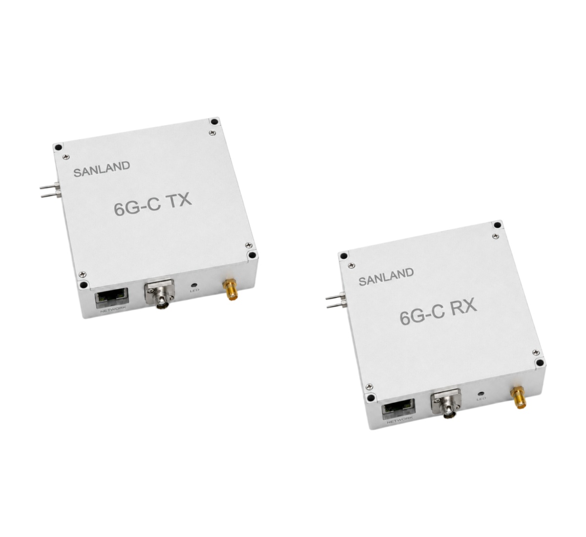
Some RF installations are located in areas where equipment cannot be accessed conveniently after deployment.
Examples include remote antenna installations, distributed RF sites, and centrally managed receiving facilities.
In these environments, the ability to adjust RF levels and monitor operating conditions can be as important as the RF transmission performance itself.
The SANLAND Remote-Controlled RFoF-C integrates RJ45 Ethernet control, programmable transmitter attenuation, selectable LNA operating modes, and RF-level and temperature monitoring.
The transmitter provides 0–31 dB attenuation adjustment in 1 dB steps.
The two LNA operating modes serve different signal conditions:
| Parameter | LNA OFF | LNA ON |
|---|---|---|
| Nominal link gain | 6 dB | 36 dB |
| Noise figure | 29 dB | 8 dB |
| Input P1dB | −5 dBm | −35 dBm |
| SFDR | 103 dB·Hz²⁄³ | 98 dB·Hz²⁄³ |
LNA ON offers higher gain and a lower noise figure, making it relevant to low-level signal reception. However, its lower input compression point requires careful attention to signal strength.
LNA OFF provides higher input-power handling and may be more appropriate when the received RF signal is relatively strong.
When to consider RFoF-C: Choose this architecture when remote adjustment, operating-condition monitoring, or selectable RF gain modes are important system requirements.
Compact Analog/Digital RFoF: For Integration and Configuration Flexibility

Equipment manufacturers and RF system developers often face constraints involving enclosure space, power supply architecture, optical connectivity, and module integration.
For these applications, physical size and configuration options may influence product selection as much as the RF performance.
The SANLAND Compact Analog/Digital RFoF is a 64 × 39 × 12 mm module designed for transparent transmission of analog and digitally modulated RF signals.
It operates from a nominal 5 V supply and provides a 50 Ω SMA RF interface.
Its published RF characteristics include 20 dB link gain, 33 dBm typical IIP3, and an SFDR range of 90–104 dB·Hz²⁄³.
The product is available in transmitter, receiver, and pair configurations, with 1310 nm or 1550 nm wavelength options and multiple optical connector choices.
The flexibility can be useful when integrating RFoF functionality into an existing RF platform or developing equipment with particular mechanical and optical interface requirements.
When to consider Compact Analog/Digital RFoF: Choose this platform when module dimensions, analog/digitally modulated RF transport, supply voltage, and optical configuration flexibility are primary design considerations.
Plug-and-Play Analog RFoF: For Straightforward Point-to-Point Transmission
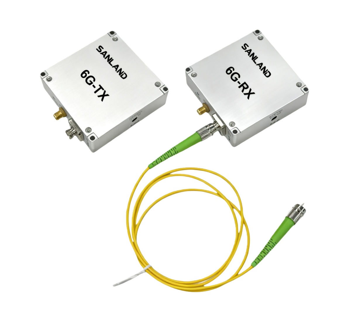
Not every RF system requires software-based configuration or continuous remote monitoring.
For fixed installations with defined RF input conditions, a simpler point-to-point architecture may be preferable.
The SANLAND Plug-and-Play Analog RFoF consists of a 6G-TX transmitter and a 6G-RX receiver connected through single-mode fiber.
The link provides 20 dB nominal gain without requiring an external control interface.
Published characteristics include 104 dB·Hz²⁄³ SFDR, 16 dB noise figure, and ±0.25 dB gain flatness over any 36 MHz bandwidth.
This architecture eliminates the need to integrate Ethernet-based gain control or monitoring into the RF transport system.
It can also carry suitable modulated RF waveforms within its operating limits. The Analog RFoF product designation should not be interpreted as a restriction to unmodulated signals.
When to consider Plug-and-Play Analog RFoF: Choose this architecture when the RF operating conditions are already defined and a fixed-gain, easy-to-deploy transmission link is preferred.
5. RFoF Selection Matrix: Which Solution Fits Your Requirements?
The following table summarizes how the three architectures address different engineering priorities.
| Primary Requirement | Recommended Starting Point | Reason |
|---|---|---|
| Remote gain adjustment and monitoring | RFoF-C | Ethernet control, programmable attenuation, RF and temperature monitoring |
| Selectable LNA operating modes | RFoF-C | Different gain, noise, and input-handling characteristics |
| Space-constrained equipment integration | Compact Analog/Digital | 64 × 39 × 12 mm module |
| Explicit analog/digitally modulated RF support | Compact Analog/Digital | Designed and specified for both signal formats |
| Flexible optical connector configuration | Compact Analog/Digital | Multiple connector options |
| Simple point-to-point analog RF transport | Plug-and-Play | Fixed-gain operation without external control |
| Narrowband gain-flatness priority | Plug-and-Play | ±0.25 dB over any 36 MHz, subject to full link requirements |
This matrix is a starting point rather than a substitute for detailed technical evaluation.
For instance, a compact module may appear attractive for a remote outdoor system, but its specified operating temperature range of −20°C to +50°C must be considered. RFoF-C and the Plug-and-Play series specify operating ranges from −20°C to +75°C.
Similarly, when a system requires digitally modulated RF transmission, selecting the Compact Analog/Digital series may be a logical starting point. However, the final choice should still depend on the required modulation quality, signal levels, bandwidth, and link performance.
6. Three Practical RFoF Selection Scenarios
Understanding the differences becomes easier when the selection process is applied to real engineering requirements.
Scenario A: An Unattended Remote RF Receiving Site
An RF receiving station is installed away from the main equipment room. Its incoming signal level may change with operating conditions, and routine site visits are inconvenient.
The system designer needs to adjust attenuation and observe RF levels from a central location.
In this case, RFoF-C is a logical candidate because it supports Ethernet-based control and monitoring.
The engineer must still confirm which LNA mode provides the appropriate balance of noise performance and input-power handling.
Scenario B: A Compact RF Distribution Equipment Design
An equipment manufacturer needs to integrate RF-over-fiber transmission into a small enclosure.
The equipment operates from a 5 V supply and must transport digitally modulated RF carriers.
Module dimensions, available RF interfaces, and optical connector options are major design constraints.
The Compact Analog/Digital RFoF is a suitable starting point because it combines small dimensions with flexible integration options.
Before finalizing the design, the manufacturer should verify the signal input range, expected modulation performance, and operating temperature conditions.
Scenario C: A Fixed RF Link Between Two Locations
A system requires a direct RF connection between two equipment locations.
The frequency range and signal levels are well defined, and no remote gain adjustment or Ethernet monitoring is required.
The primary objective is straightforward deployment with suitable RF performance.
The Plug-and-Play Analog RFoF may be the more appropriate architecture.
The engineer should verify the optical path loss, input compression margin, and recovered RF output before deployment.
These examples illustrate an important principle: the best RFoF solution is determined by the complete system requirement, not simply the industry in which it will be used.
7. Common RFoF Selection Mistakes to Avoid
Several frequently overlooked factors can affect an RFoF project even when the advertised frequency range appears suitable.
Choosing a link based only on maximum frequency. Two products covering 5 MHz–6 GHz may differ in gain, noise figure, compression behavior, and optical configuration.
Assuming higher gain always improves performance. Higher gain can help with low-level signals, but it may also reduce the margin available for strong input signals or overload downstream equipment.
Confusing optical power with RF output power. Optical transmitter power does not directly specify the electrical RF output level recovered at the receiver.
Assuming maximum distance from wavelength alone. The usable distance depends on optical link loss and the required RF performance. Fiber distance should be evaluated against the complete optical power budget.
Overlooking environmental requirements. Module size, supply voltage, operating temperature, and mechanical installation can determine whether a product is suitable for a particular system.
Assuming a single TX/RX pair provides bidirectional RF transport. A standard transmitter-receiver pair provides one transmission direction. Bidirectional applications require an appropriately designed return path.
Addressing these issues during initial selection can reduce the likelihood of additional hardware changes or unexpected RF performance problems during system integration.
8. RFoF Selection Checklist: What Information Should You Prepare?
Before contacting an RFoF supplier or evaluating a transmitter/receiver pair, prepare the following information:
| Required Information | What to Specify |
|---|---|
| RF frequency range | Lowest and highest frequencies |
| Signal type | CW, analog, digitally modulated, or multicarrier RF |
| RF input level | Minimum, typical, and maximum input power |
| Required RF output | Target output level and allowable variation |
| Signal quality | Noise, linearity, flatness, or modulation-quality requirements |
| Fiber distance | Approximate transmission distance and known path loss |
| Optical interface | Wavelength, fiber type, and connector |
| Link configuration | One-way or bidirectional transmission |
| Control requirements | Fixed operation or remote adjustment and monitoring |
| Installation conditions | Supply voltage, dimensions, and operating temperature |
For digitally modulated RF, it is also useful to specify the modulation format, occupied bandwidth, and applicable EVM or other signal-quality limits.
Providing this information allows the RFoF link to be evaluated against the actual system requirements rather than relying on general product specifications.
Frequently Asked Questions
How do I choose between a fixed-gain and remotely controlled RFoF link?
A fixed-gain link is often suitable when the input signal level and operating conditions are stable and well defined. Remote-controlled RFoF becomes more useful when signal levels vary, gain adjustments are required, or equipment needs to be monitored from another location.
Can RFoF carry digitally modulated RF signals?
Yes. Analog RF-over-fiber transmission can transport digitally modulated RF waveforms if the link provides adequate frequency coverage, linearity, noise performance, and power handling. SANLAND's Compact Analog/Digital RFoF is specifically positioned for this type of transmission. Other RFoF architectures should be evaluated against the actual modulation-quality requirements.
Is a 5 MHz–6 GHz RFoF link suitable for satellite communications?
It can transport satellite IF or downconverted RF signals that fall within its supported frequency range. Higher-frequency antenna signals, such as Ku-band or Ka-band RF, require appropriate frequency conversion before entering a 6 GHz-limited RFoF link.
How far can an RFoF link transmit?
There is no single distance applicable to every installation. Maximum usable distance depends on optical transmitter power, receiver operating range, fiber attenuation, connector and splice losses, and the RF performance required at the receiving end. A link-budget evaluation is necessary to determine the appropriate configuration.
Conclusion: Select RFoF Based on Your System, Not Just Its Frequency Range
Selecting an RF over fiber solution requires a balance between RF performance, optical configuration, integration requirements, and operational flexibility.
A remotely managed receiving station may benefit from programmable attenuation and real-time monitoring. An embedded RF platform may prioritize compact dimensions and interface flexibility. A fixed point-to-point installation may favor a straightforward plug-and-play architecture.
Although all three SANLAND RFoF solutions support transmission across 5 MHz–6 GHz, each addresses a different set of engineering priorities.
The most reliable selection process starts by defining the RF signal, establishing the required link performance, and confirming the optical and environmental conditions before choosing the hardware.
Explore the complete SANLAND 5 MHz–6 GHz RF Over Fiber Series to compare the available architectures and specifications.
For projects with specific RF transmission requirements, the frequency range, signal levels, fiber distance, optical configuration, and control options should be evaluated together. If further technical clarification is needed, you can to discuss the requirements of your application.